
Removing solids from a fluid

a fluid and solids technology, applied in the direction of liquid degasification, auxillary pretreatment, separation processes, etc., can solve the problems of low separation efficiency, relatively high maintenance apparatus, and about five micron sized particles that can be separated by conventional cyclone separators

Inactive Publication Date: 2001-08-28
TWISTER BV
View PDF27 Cites 66 Cited by
  • Summary
  • Abstract
  • Description
  • Claims
  • Application Information

AI Technical Summary

Benefits of technology

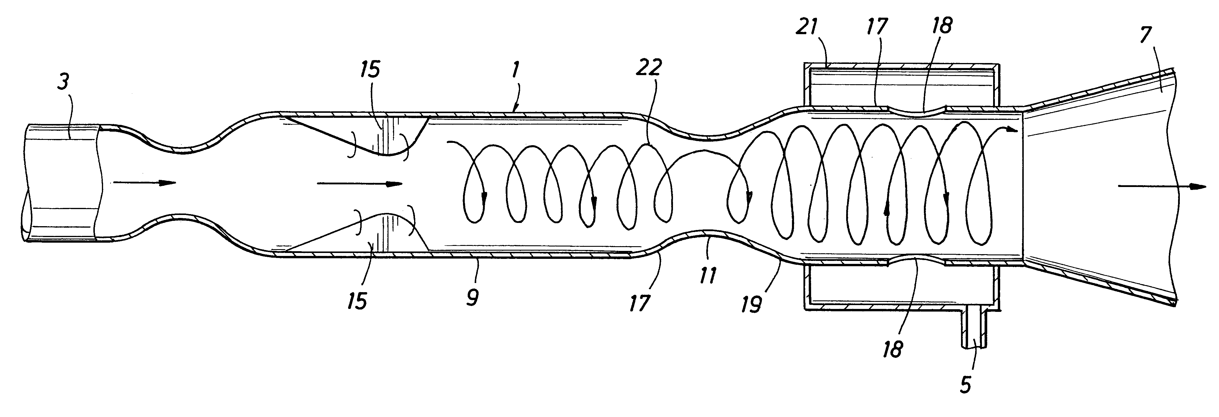
In a preferred embodiment of the present invention, a shock wave caused by transition from supersonic to subsonic flow occurs upstream of the separation of the solids from the collecting zone. It was found that the separation efficiency is significantly improved if collection of the particles in the collecting zone takes place after the shock wave, i.e. in subsonic flow rather than in supersonic flow. This is because the shock wave dissipates a substantial amount of kinetic energy of the stream and thereby strongly reduces the axial component of the fluid velocity while the tangential component (caused by the swirl imparting means) remains substantially unchanged. As a result the density of the particles in the radial outer section of the collecting zone is significantly higher than elsewhere in the conduit where the flow is supersonic. It is believed that this effect is caused by the strongly reduced axial fluid velocity and thereby a reduced tendency of the particles to be entrained by a central "core" of the stream where the fluid flows at a higher axial velocity than nearer the wall of the conduit. Thus, in the subsonic flow regime the centrifugal forces acting on the condensed particles are not to a great extent counteracted by the entraining action of the central "core" of the stream, so that the particles are allowed to agglomerate in the radially outer section of the collecting zone from which they are extracted.
The supersonic flow of the present invention also causes a rapid expansion, resulting in cooling of a compressible fluid stream. This cooling results in condensation of vapors to the extent that such cooling brings the temperature of the stream to a temperature below a dew point of the fluid stream. Creation of this liquid can improve separation of solids from the fluids by providing surfaces to which the solids can agglomerate, resulting in larger particles that are more easily separated.

Problems solved by technology

Practically, only about five micron sized particles can be separated by conventional cyclone separators.
This high rotational speed results in a relatively high maintenance apparatus.
Furthermore, the separation efficiency is relatively low so that substantial amounts of the condensed particles are still present in the second outlet stream.

Method used


Image

  • Removing solids from a fluid
  • Removing solids from a fluid
  • Removing solids from a fluid

Examples


second embodiment

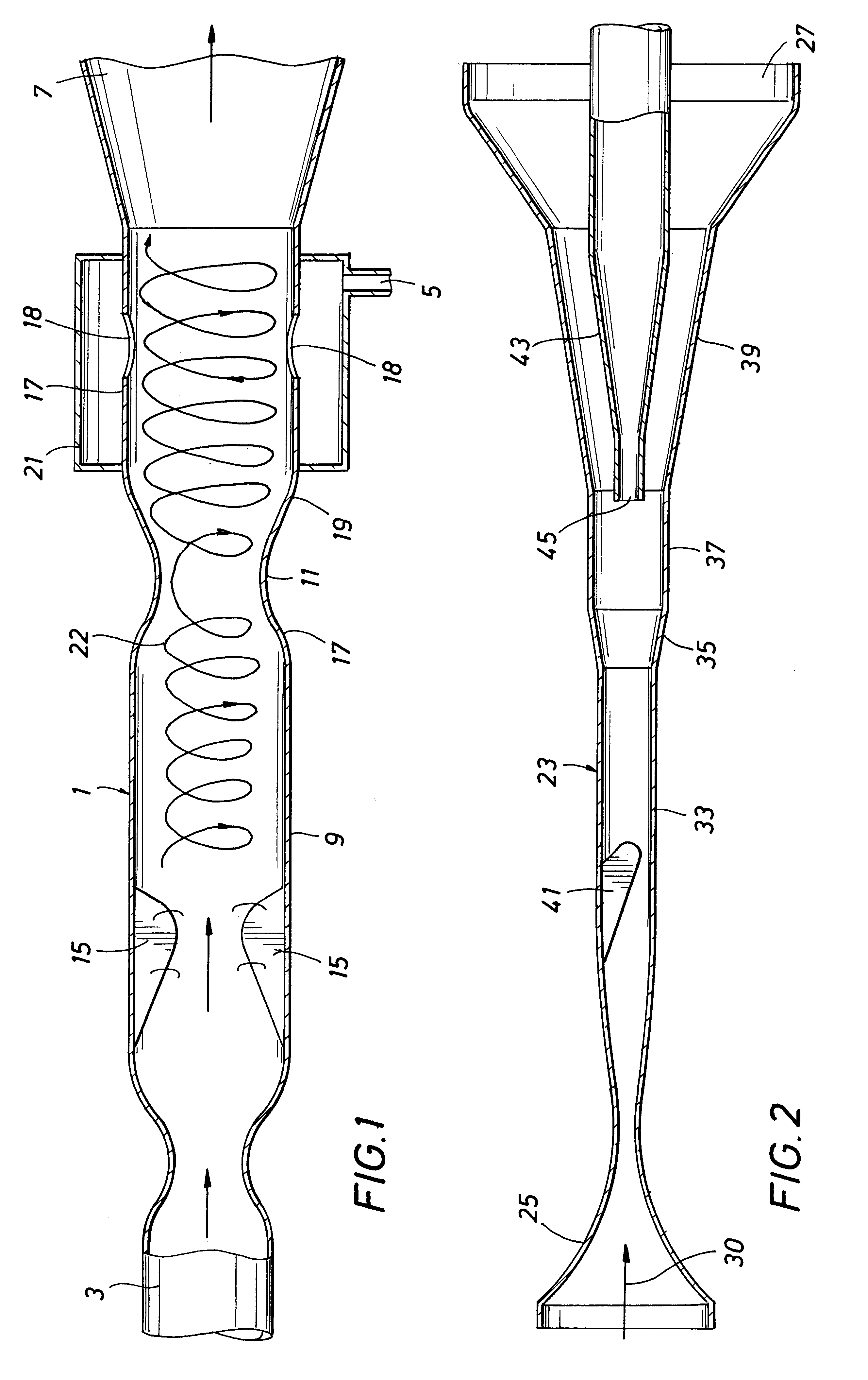
In FIG. 2 is shown the device for carrying out the invention, the device having an open-ended tubular housing 23 with a Laval-type fluid inlet 25 at one end and a first outlet 27 for stream containing the solids and any condensed liquid at the other end of the housing. The flow-direction for fluid in the device is indicated by arrow 30. The housing has, from the inlet 25 to the liquid outlet 27, a primary substantially cylindrical part 33, a diverging diffuser 35, a secondary cylindrical part 37 and a diverging part 39. A delta-shaped wing 41 projects radially inward in the primary cylindrical part 33, the wing 37 being arranged at a selected angle to the flow-direction in the housing so as to impart a swirling motion to fluid flowing at supersonic velocity through the housing 23. A tube-shaped second outlet 43 for substantially gas extends through the first outlet 27 coaxially into the housing, and has an inlet opening 45 at the downstream end of the secondary cylindrical part 37. ...

example

A test apparatus for the present invention was prepared, and demonstrated for separating water vapor from air at ambient conditions. This apparatus and exemplary tests are described below, and this example along with application of Stokes law would demonstrate the application of the present invention as applied to separation of particles from a gas stream, either along with separation of condensable gases or without separation of condensable gases.

A test apparatus for the present invention was prepared, and demonstrated for separating water vapor from air at ambient conditions. FIG. 4 is referred to for the general configuration of the apparatus used.

In this example the air 425 is pressurized to 1.4 bar(abs.) by means of a blower 401 to provide pressurized air 426. After the blower the air is cooled to about 25 to 30.degree. C. by fin cooler 402, located in a vessel 418, and water 419 is sprayed into the vapor space below the cooler 420 to ensure that the air is near water saturatio...


PUM

PropertyMeasurementUnit
thicknessaaaaaaaaaa
mean droplet diameteraaaaaaaaaa
throat diameteraaaaaaaaaa

Abstract

A method and apparatus are provided for removing solid particles from a particle containing stream of fluid, the method including the steps of: inducing the stream to flow at supersonic velocity through a conduit; inducing a swirling motion to the supersonic stream of fluid thereby causing the particles to flow to a radially outer section of a collecting zone in the stream; and extracting the solid particles into an outlet stream from the radially outer section of the collecting zone. The apparatus is an apparatus effective for performance of this method.

Description

The present invention relates to removing solids from a fluid.BACKGROUND TO THE INVENTIONCentrifugal force is useful for separation of solids from streams of fluids. Such separation can find application in various industrial processes, for example in removing of catalyst particles in fluidized bed catalytic cracking operations, and separation of ash from flue gases.Fluids, when rotating around a central axis, will be accelerating toward the central axis, and inertia of the solids will force the solids outward away from the central axis. Outward flow of particles will be against the flow of fluids. Fluids containing fewer solids are then typically withdrawn from the center axis of rotation, and the solids are removed from the radially outer surface of the separator. The rate of flow of solids outward is limited by the resistance of the fluid. This rate is dictated by Stokes Law. Practically, only about five micron sized particles can be separated by conventional cyclone separators.U....

Claims


Application Information

Patent Timeline
Patent Type & Authority Patents(United States)
IPC IPC(8): B01D45/16B01D45/12B01D5/00B01D51/00B01D51/08B01D19/00B04C3/00
CPCB01D5/0021B01D19/0078B04C3/00B01D51/08B01D45/16
Inventor VAN VEEN, J. W. H. M.BETTING, MARCO
Owner TWISTER BV
Learn More