Method of producing magnetic force image and scanning probe microscope

a scanning probe and magnetic force technology, applied in the direction of mechanical roughness/irregularity measurement, magnetic field measurement using permanent magnets, instruments, etc., can solve the problems of deteriorating spatial resolution and difficult to improve the resolution of magnetic force image further

Inactive Publication Date: 2001-08-28
JEOL LTD
View PDF2 Cites 25 Cited by
  • Summary
  • Abstract
  • Description
  • Claims
  • Application Information

AI Technical Summary

Problems solved by technology

In practice, however, the spatial resolution is deteriorated because the distance between the sample and the tip is increased.
Accordingly, in this lift mode operation, it is difficult to improve the resolution of the magnetic force image further.

Method used


Image

  • Method of producing magnetic force image and scanning probe microscope
  • Method of producing magnetic force image and scanning probe microscope
  • Method of producing magnetic force image and scanning probe microscope

Examples


Embodiment Construction

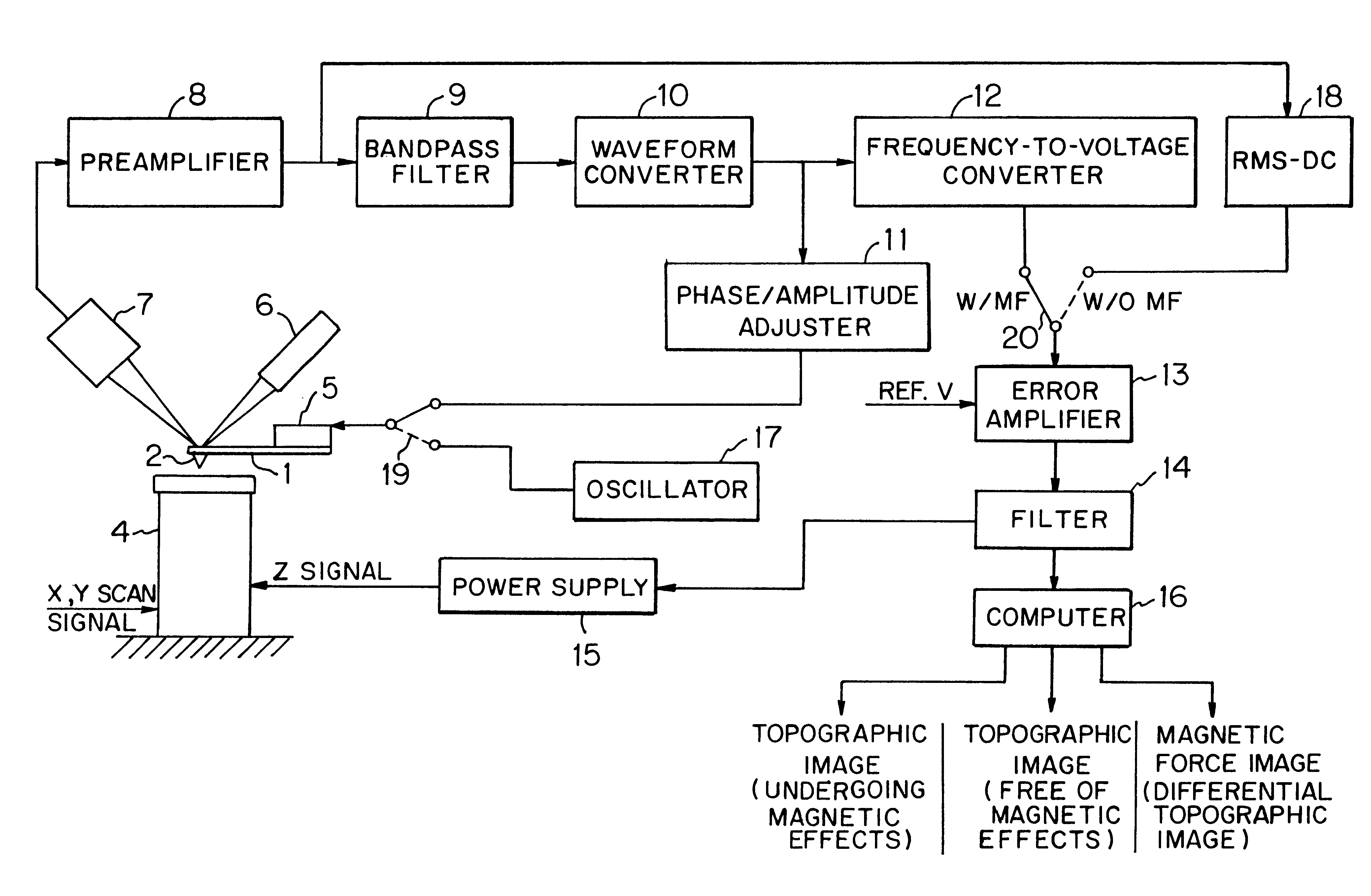
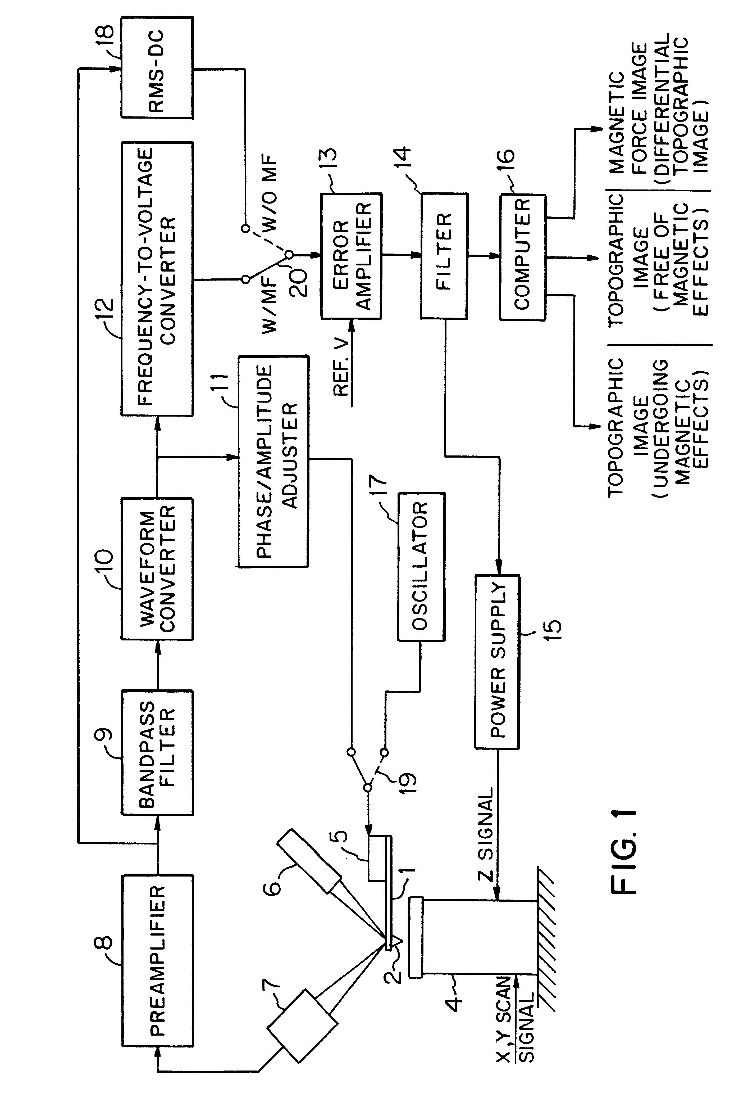
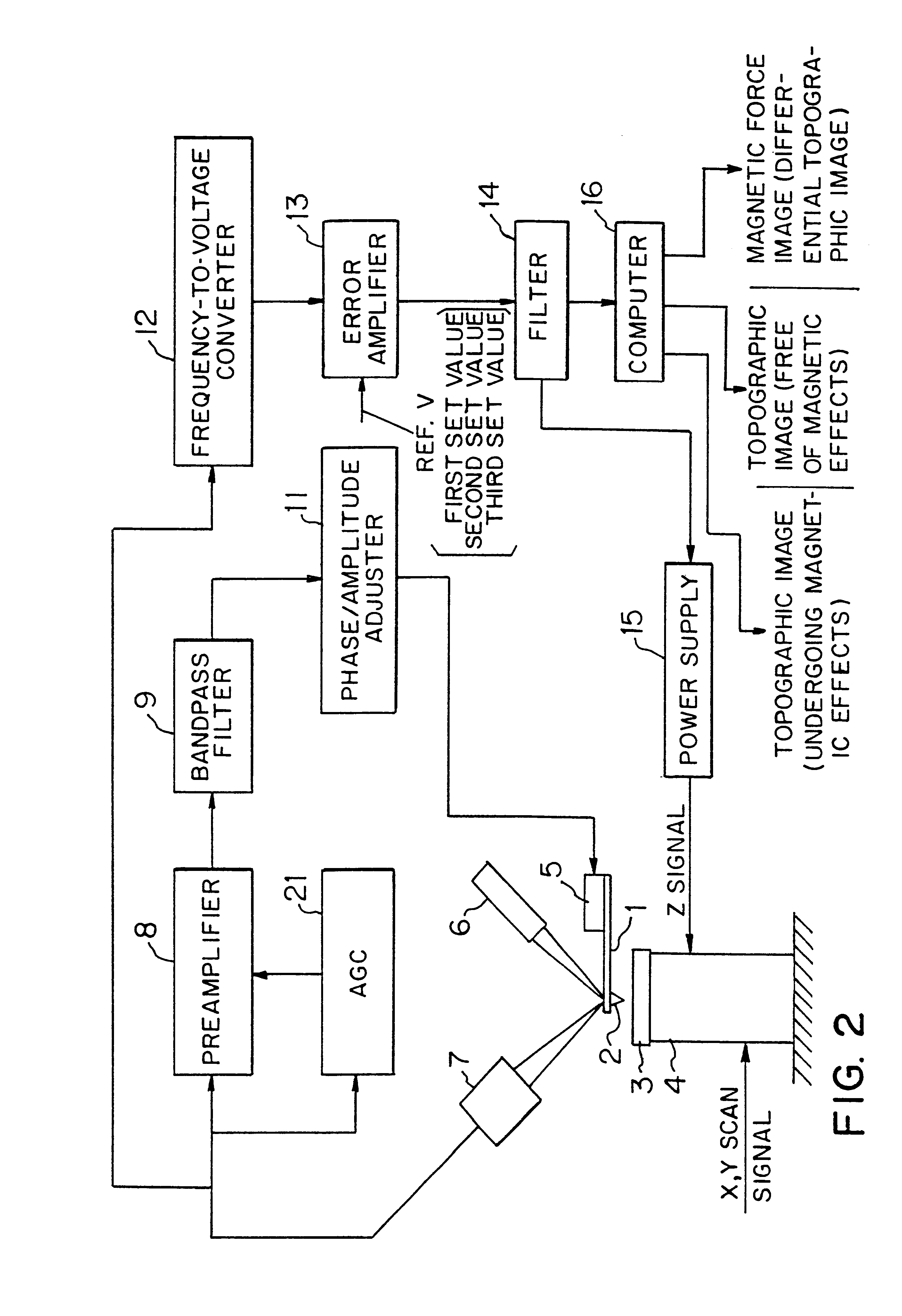
Referring to FIG. 1, there is shown a scanning probe microscope embodying the concept of the present invention. This scanning probe microscope (SPM) is fitted with a cantilever having a resonance frequency. This microscope produces a first topographic image of a surface of a sample from the resonance frequency of the cantilever by FM detection. This first topographic image feels magnetic effects. The microscope also produces a second topographic image from the amplitude of the cantilever by slope detection. This second image receives no magnetic effects. The difference between these two topographic images is found to produce a magnetic force image of the sample.

In recent years, a cantilever having a relatively large spring constant has been used in ultrahigh vacuum, thus permitting imaging of atoms by noncontact AFM. The surface of the sample having magnetic forces is imaged by FM detection. Thus, a high-resolution topographic image undergoing magnetic effects is produced. Slope det...


PUM

PropertyMeasurementUnit
magnetic forceaaaaaaaaaa
resonance frequencyaaaaaaaaaa
constant frequencyaaaaaaaaaa

Abstract

There is disclosed a scanning probe microscope for producing a topographic image of a surface of a sample by noncontact AFM (atomic force microscopy). First, a first topographic image of the sample undergoing magnetic effects is produced from the resonance frequency of a cantilever by FM detection. Then, a second topographic image of the sample free of magnetic effects is produced from the amplitude of the cantilever by slope detection. The difference between these two topographic images is taken. Thus, a magnetic force image is produced.

Description

The present invention relates to scanning probe microscopy (SPM) techniques using a noncontact atomic force microscope (AFM) which receives forces from a sample and produces a topographic image of the surface of the sample and which is also capable of detecting magnetic forces from the sample by magnetic force microscopy (MFM) utilizing the functions of the noncontact AFM.DESCRIPTION OF THE PRIOR ARTScanning probe microscopy has been heretofore developed which images the topography of the surface of a sample by the function of noncontact AFM by measuring a physical force produced between a tip and the sample and which can also detect the magnetic force from the sample by the functions of MFM. In this conventional SPM, the magnetic force is a long-range force and so the magnetic force is separated from the atomic force by moving the tip or cantilever away from the sample into a position where the atomic force no longer affects the tip or cantilever; in the topography mode, the atomic...

Claims


Application Information

Patent Timeline
Patent Type & Authority Patents(United States)
IPC IPC(8): G01R33/038G12B21/00G12B21/02G01Q60/00G01N37/00G01Q60/24G01Q60/32G01Q60/34G01Q60/50H01J37/28
CPCB82Y35/00G01Q30/04G01R33/0385G01Q60/08B82Y25/00Y10S977/865Y10S977/852
Inventor KITAMURA, SHINICHI
Owner JEOL LTD
Why Eureka
Try Eureka