
Cylinder structure of internal combustion engine

a technology of internal combustion engine and cylinder, which is applied in the direction of cylinders, sealing arrangements of engines, casings, etc., can solve the problems of cooling water, lubricant oil or combustion gas leaching from the gasket 9 portion, and achieve the effect of preventing the leakage of lubricant oil or combustion gas

Inactive Publication Date: 2001-09-04
SUZUKI MOTOR CORP
View PDF8 Cites 28 Cited by
  • Summary
  • Abstract
  • Description
  • Claims
  • Application Information

AI Technical Summary

Problems solved by technology

As a result, the area between the bolt 5 and another adjacent bolt 5 provided at a given spacing the first bolt 5 becomes small in a compacting rate of a gasket 9 to cause a compacting unevenness, thereby there have been threatened for cooling water, lubricant oil or combustion gas to be leaked from the gasket 9 portion.

Method used


Image

  • Cylinder structure of internal combustion engine
  • Cylinder structure of internal combustion engine
  • Cylinder structure of internal combustion engine

Examples


Embodiment Construction

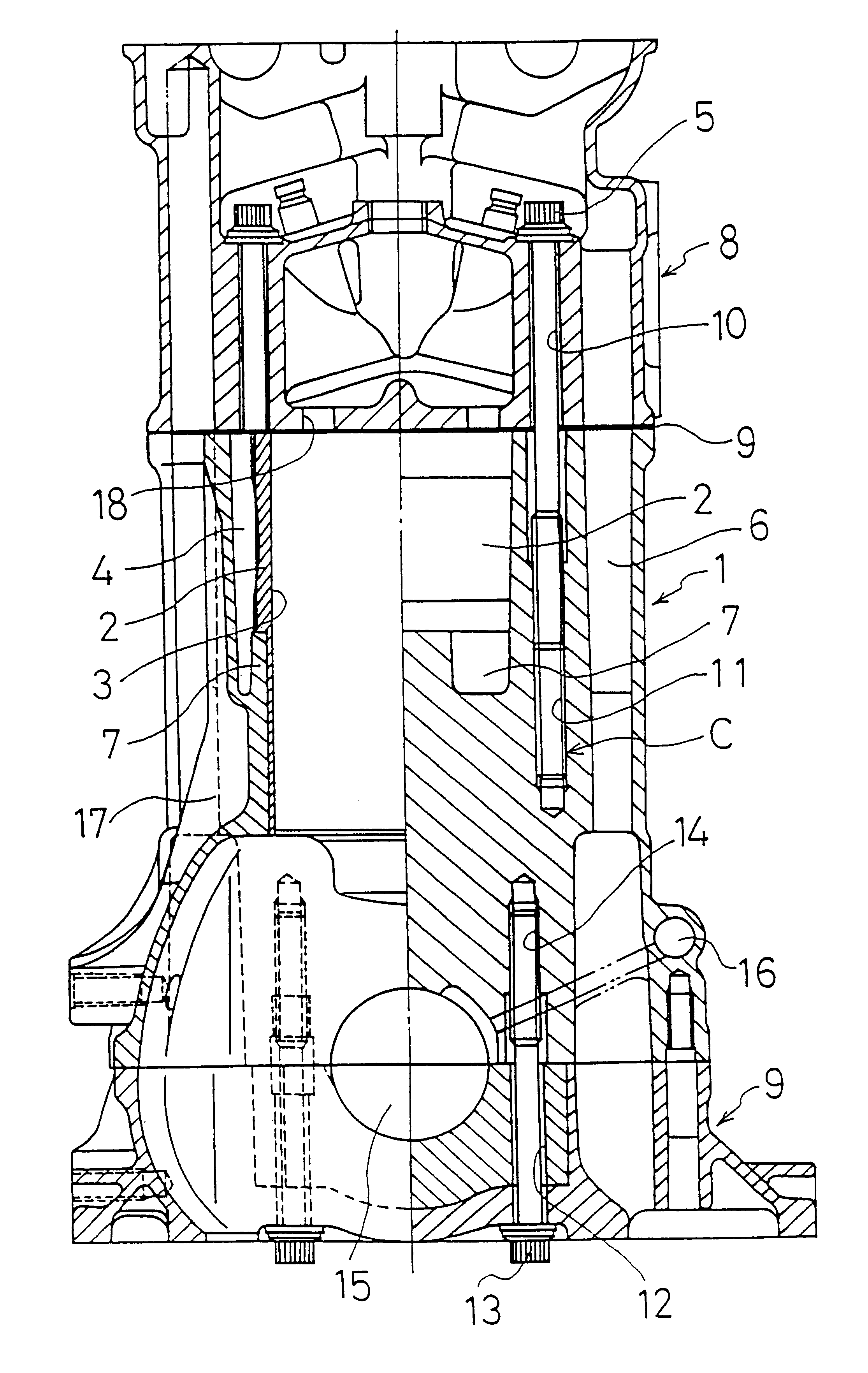
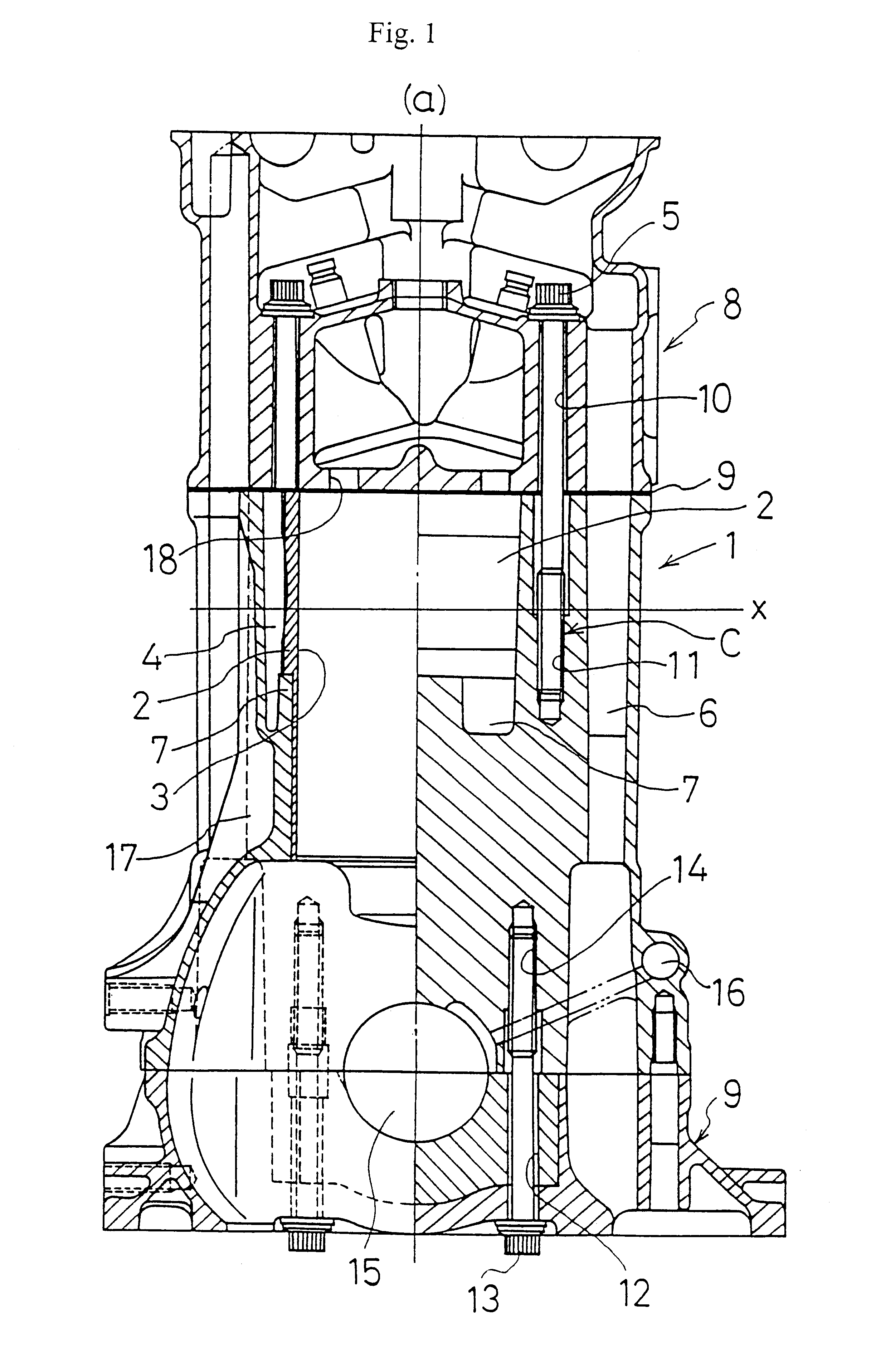
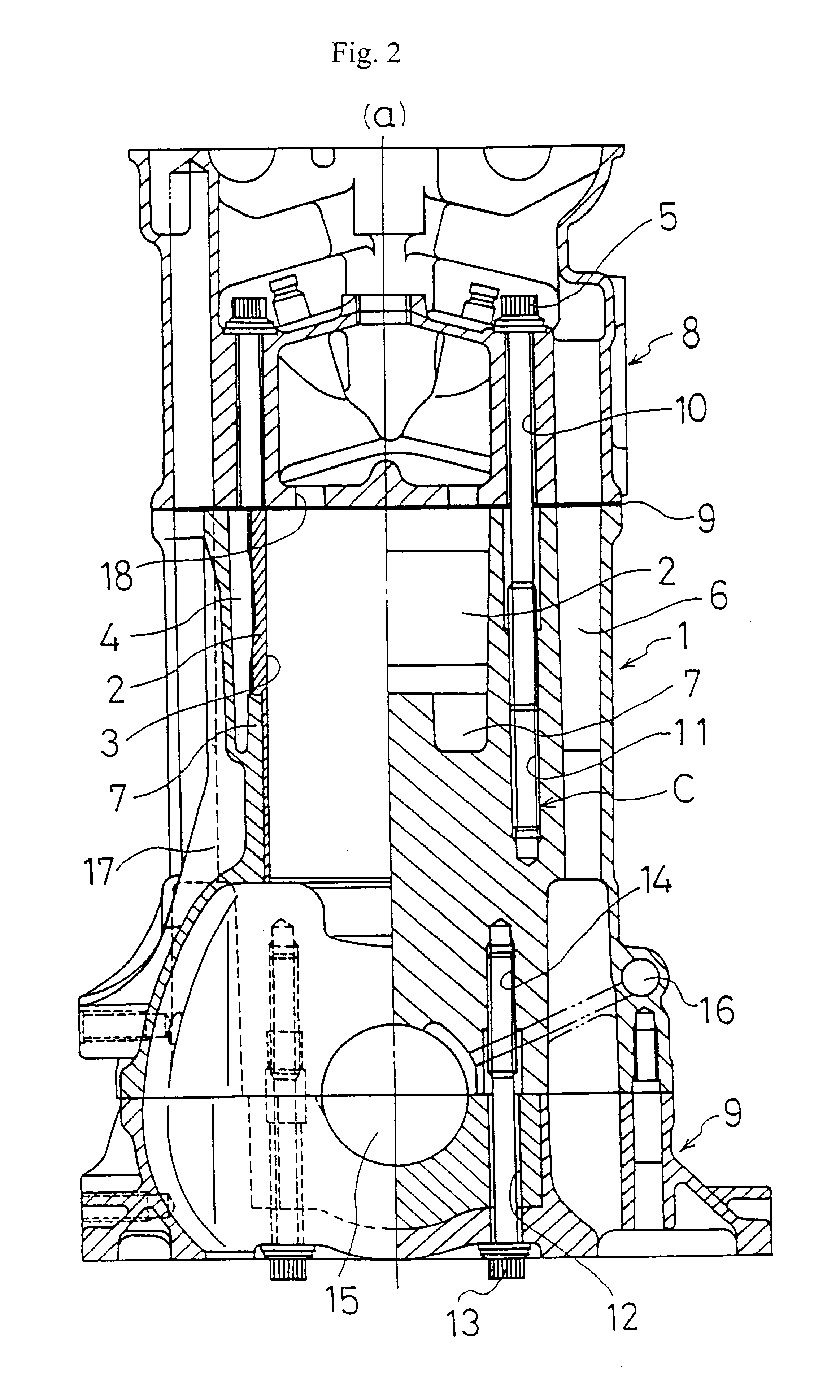
Hereinafter, an embodiment of the present invention is explained based on FIG. 1 designating identical parts of FIG. 4 in identical signs.

In this embodiment, a screw portion C of the bolt 5 (portion of screw hole 11) to the cylinder block 1 is located at the area, where a part of more than half of the screw portion C is located in such a manner as it is located under the center X of the depth of the water jacket. And this position setting is determined so as to set the screw position C of the bolt 5 to be located to the water jacket 4 provided outside the liner 2.

By thus setting the screw portion C of the bolt 5, since it is adapted to be located near at the location where a lower case 9 is connected to the cylinder block 1 with a bolt 13, the wall 17 of the blow by gas passage is located outside the area where the bolt 5 is come through and a barrel 7 for the liner is provided, which in addition is connected between each cylinder, the screw portion C of the bolt 5 is adapted to be ...


PUM


Abstract

In a combustion internal engine in which a cylinder head 8 is connected to a cylinder block 1 with a bolt 5 coming rough the cylinder head 8, more than half of a screw portion C of the bolt to be screwed in the cylinder block 1 is located under the central portion X of the depth of a water jacket 4. Since this portion of the cylinder block 1 is high in rigidity compared with the upper portion of the cylinder block, a gasket 9 can be tightened evenly.

Description

SPECIFICATIONA cylinder structure of internal combustion engine1. Technical FieldThis invention relates to a cylinder structure of an internal combustion engine for use of such as automobile.2. Background of the ArtsFIG. 3 shows a deck surface (plan view) of a cylinder block 1, and a sectional view taken along with A--A line of FIG. 3 is shown in the left side from a center line (a) in FIGS. 1, 2 and 4, and a sectional view taken along with B--B line of FIG. 3 is shown in the right side from the center line (a) in the same FIGS.In FIG, 3, reference numeral 2 shows a liner (a cylinder liner, or a sleeve), 3 designates a cylinder bore, 4 designates a water jacket, 5 designates head bolts which fasten a cylinder head (hereinafter referred as "bolts") and 6 designates an oil passage. As to bolts, a plurality of bolts 5 are provided spacing each other at a given spacing.This cylinder block 1 is of a siamese type, in which each barrel 7 (see FIGS. 1, 2 and 3) of the cylinder block is conn...

Claims


Application Information

Patent Timeline
Patent Type & Authority Patents(United States)
IPC IPC(8): F02F7/00F02F1/16F02F1/10F02F1/02F02F1/00
CPCF02F1/108F02F7/0007F02F1/16
Inventor OZEKI, HISASHI
Owner SUZUKI MOTOR CORP
Features
  • Generate Ideas
  • Intellectual Property
  • Life Sciences
  • Materials
  • Tech Scout
  • Unparalleled Data Quality
  • Higher Quality Content
  • 60% Fewer Hallucinations
Learn More