
Hall effect rotation sensor for a throttle valve unit

a technology of rotation sensor and throttle valve, which is applied in the direction of galvano-magnetic hall-effect devices, gas/liquid distribution and storage, dynamo-electric machines, etc., can solve the problems of high manufacturing and assembly costs, high assembly costs, and inability to mount the angular rotation sensor,

Inactive Publication Date: 2001-09-04
ELEKTRONIK
View PDF10 Cites 15 Cited by
  • Summary
  • Abstract
  • Description
  • Claims
  • Application Information

AI Technical Summary

Benefits of technology

Certain advantages accomplished by the invention reside in that stator elements may be configured as partial ring stator segments, and a ring magnet element may be configured as a partial ring magnet segment. Such a design advantageously saves material. The integration of these parts into units of an angular rotation sensor makes subsequent adjustments unnecessary, saving valuable assembly time. The special configuration of the partial ring magnet segment and a three-piece division of the stator into three partial ring stator segments (and their special correlation with each other) constitutes an advantageous design of an angular rotation sensor. Such a design makes highly precise measurements possible.
The toothed wheel segment may be made from plastic material into which the ring magnet may be molded. The cap housing element may also be made from plastic material into which the partial stator ring segments or the subdivided partial stator ring segments may be at least partially molded. This secures the structural integration of these parts that are very important for the function and measuring precision of the angular rotation sensor. In this manner, production effort is reduced to a minimum. These elements may be precisely adjusted, making subsequent adjustments superfluous.

Problems solved by technology

Although this adjusting device has exhibited at least a degree of utility, its assembly expense may be very high.
In addition, it is not possible to mount the angular rotation sensor, the motor, and the transmission easily on different types of throttle valve units.
While this configuration reduces the quantity of material needed to produce these parts, manufacturing and assembly costs may be very high.
The integration of these parts into units of an angular rotation sensor makes subsequent adjustments unnecessary, saving valuable assembly time.

Method used


Image

  • Hall effect rotation sensor for a throttle valve unit
  • Hall effect rotation sensor for a throttle valve unit
  • Hall effect rotation sensor for a throttle valve unit

Examples


Embodiment Construction

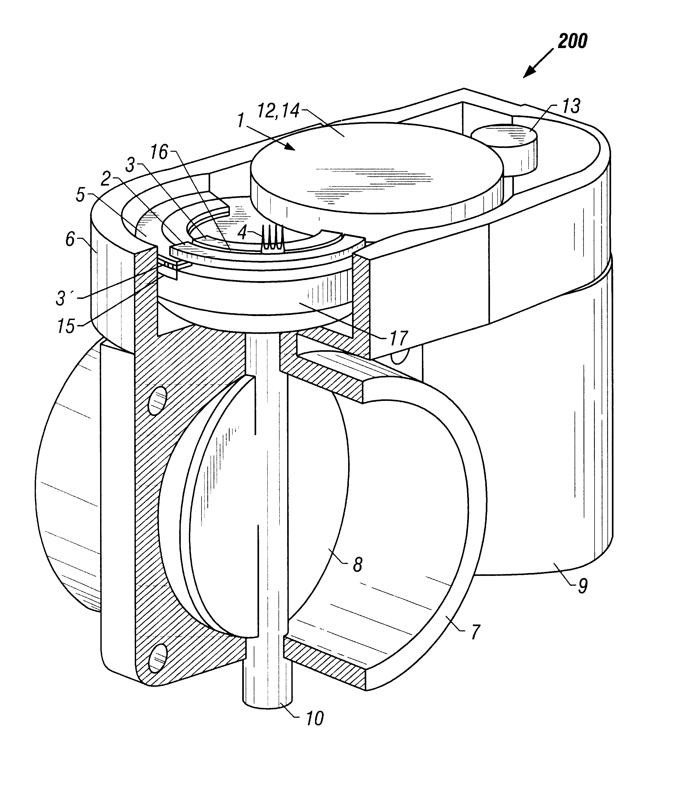
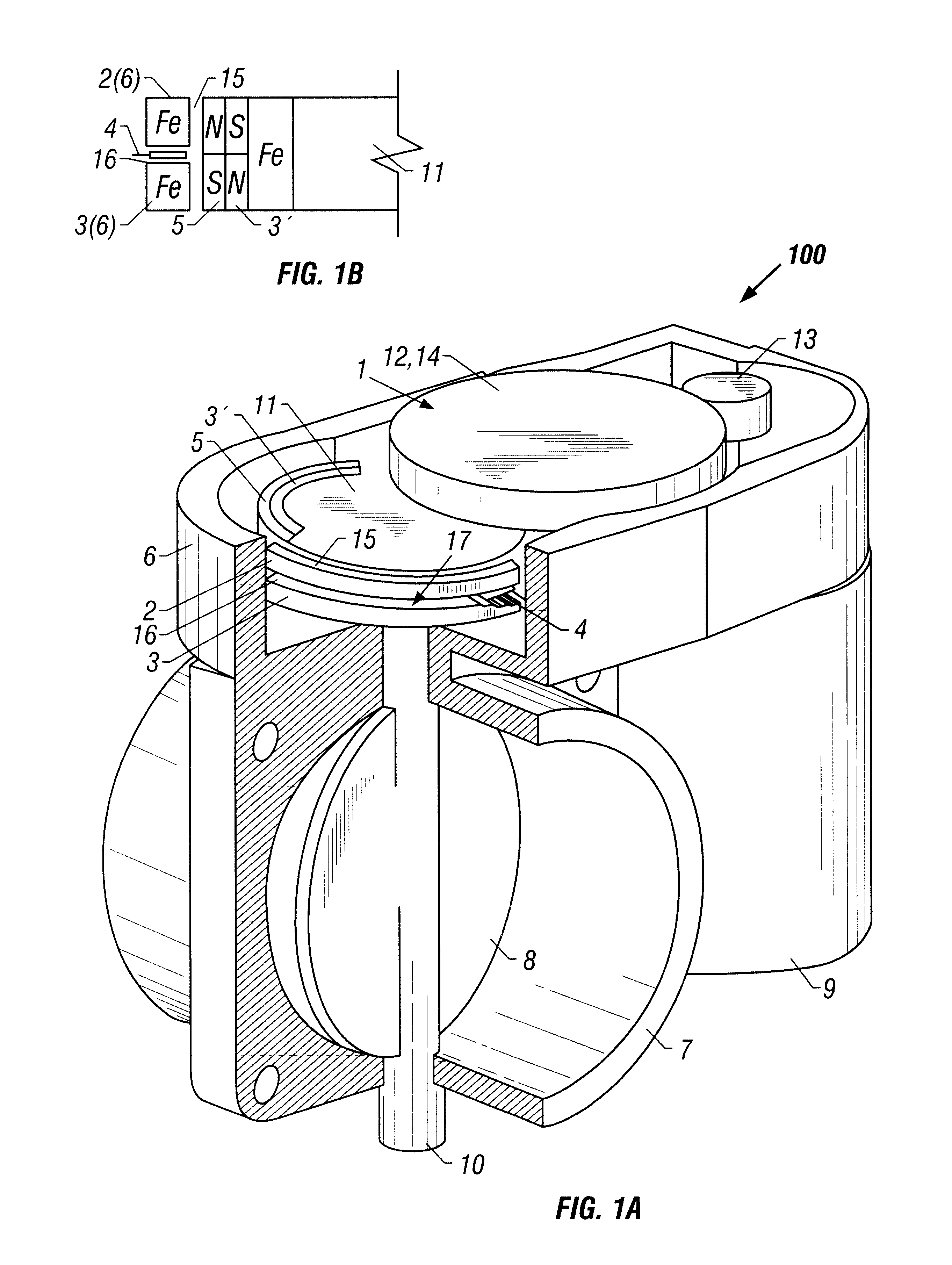
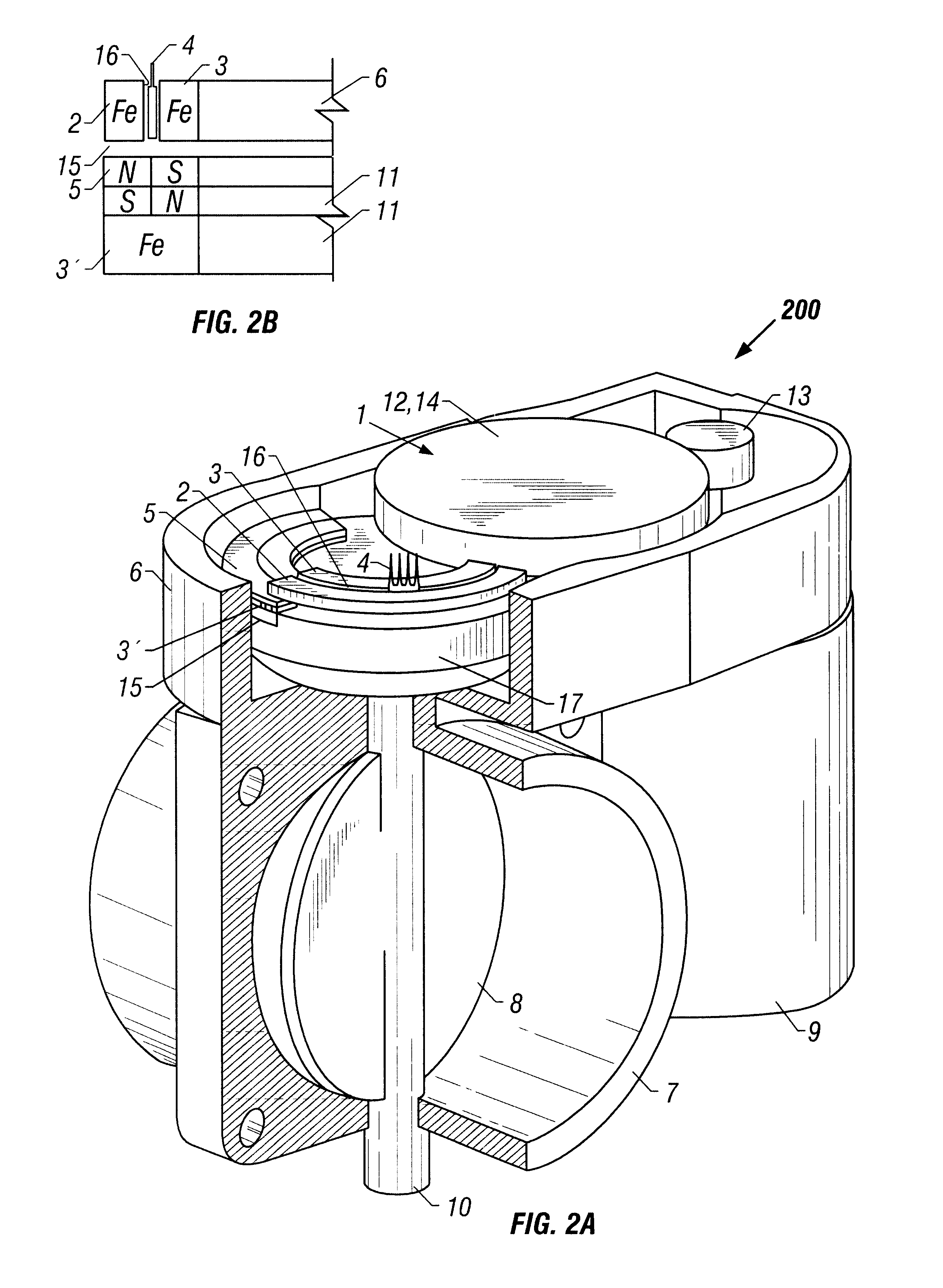
In FIG. 1a, a throttle valve angular rotation sensor is shown with an angular rotation sensor device 100. It includes an angular rotation sensor device and a throttle valve unit including a throttle valve housing 7 and a throttle valve 8 that is retained in the throttle valve housing 7 and can be adjusted via a throttle valve shaft 10. A sensor housing element 6, which carries a motor 9, is arranged on the throttle valve housing 7. The sensor housing element 6 may, in one embodiment, be manufactured as an enclosed component but it will be understood that it may be manufactured in many different manners. For instance, in another embodiment, it may be manufactured as an open component, as shown in FIG. 1a, that may be subsequently closed with a separate cap.

The sensor housing element 6 contains a transmission 1, a stationary unit 2, 3, 4, and a rotating unit 3', 5 of an angular rotation sensor. The transmission 1 may be configured as a conventional transmission or as a planetary gear....


PUM


Abstract

A Hall-effect angular rotation sensor device for a throttle valve unit. The sensor includes a housing unit, a stationary unit, and a moving unit moveable relative to the stationary unit. The stationary and the moving units are at least partially enclosed by the housing unit. The stationary unit includes a first and a second partial ring stator segment that are at least partially retained in the housing unit, leaving a stator distancing gap in which at least one Hall-effect IC switch is positioned. The moving unit includes (a) a partial ring magnet segment that is at least partially distanced from the first and the second partial ring stator segments by an air gap and (b) a third partial ring stator segment positioned behind and opposite the air gap.

Description

1. Field of the InventionThe present invention relates generally to the field of position devices. More particularly, it concerns a position device for a throttle valve unit, in which a throttle valve held by a throttle valve shaft is arranged adjustably in a housing unit that includes at least one Hall-effect angular rotation sensor unit that is arranged on the throttle valve unit. The sensor unit includes a stationary unit, a moving unit that can be moved relative to the stationary unit, a drive unit, and a transmission that is arranged between the moving unit and the drive unit. The housing unit encloses, at least partially, the stationary unit and the moving unit. Even more particularly, the invention concerns a Hall-effect angular rotation sensor device that includes a stationary unit and a moving unit that can be moved relative to the stationary unit. The housing unit encloses, at least partially, the stationary unit and the moving unit.The present invention also relates gener...

Claims


Application Information

Patent Timeline
Patent Type & Authority Patents(United States)
IPC IPC(8): F02D9/08F02D9/10F02D11/10H02K29/06H02K29/08F02D9/02G01D5/14
CPCF02D9/105F02D11/106F02D2009/0294G01D5/145H02K29/08Y10T137/8242
Inventor APEL, PETERWILCZEK, KLAUS
Owner ELEKTRONIK
Learn More