Battery cell charging system having voltage threshold and bleeder current generating circuits

a battery cell and charging circuit technology, applied in the direction of electrochemical generators, secondary cell servicing/maintenance, transportation and packaging, etc., can solve the problems of reducing the manufacturing efficiency of battery cells, reducing the manufacturing efficiency of batteries, and only providing a rough approximation of individual cell voltages

Inactive Publication Date: 2001-09-04
O2 MICRO INT LTD
View PDF5 Cites 66 Cited by
  • Summary
  • Abstract
  • Description
  • Claims
  • Application Information

AI Technical Summary

Problems solved by technology

More particularly, certain types of nonaqueous electrolyte battery cells, such as lithium ion cells, are susceptible to damage if charged to too high a voltage or permitted to be discharged to too low a voltage.
However, this technique provides only a rough approximation of the individual cell voltage since typically, the voltage across each cell varies somewhat.
Moreover, use of plural sensing circuits results in disadvantageous component duplication and...

Method used


Image

  • Battery cell charging system having voltage threshold and bleeder current generating circuits
  • Battery cell charging system having voltage threshold and bleeder current generating circuits
  • Battery cell charging system having voltage threshold and bleeder current generating circuits

Examples


Embodiment Construction

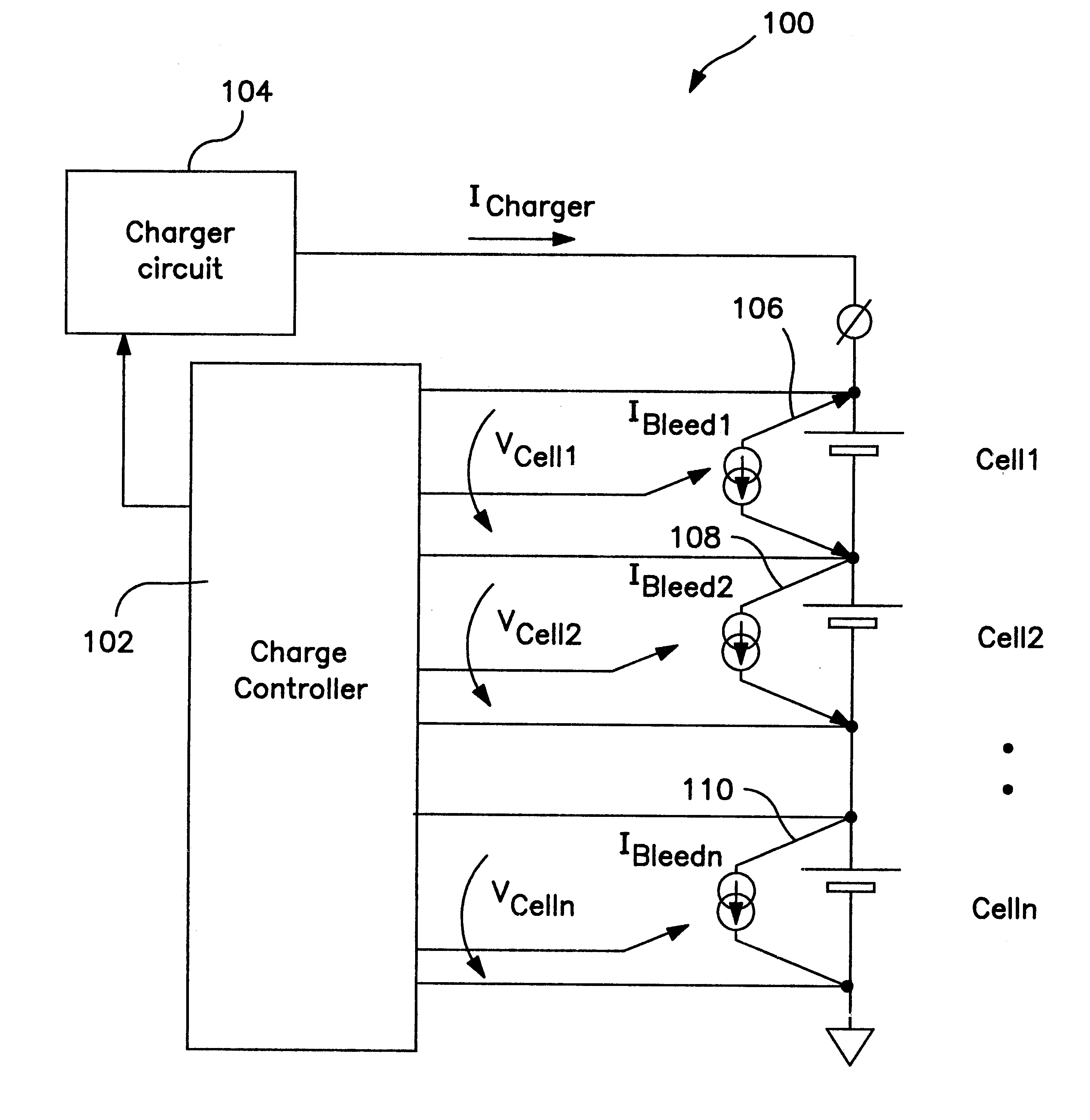
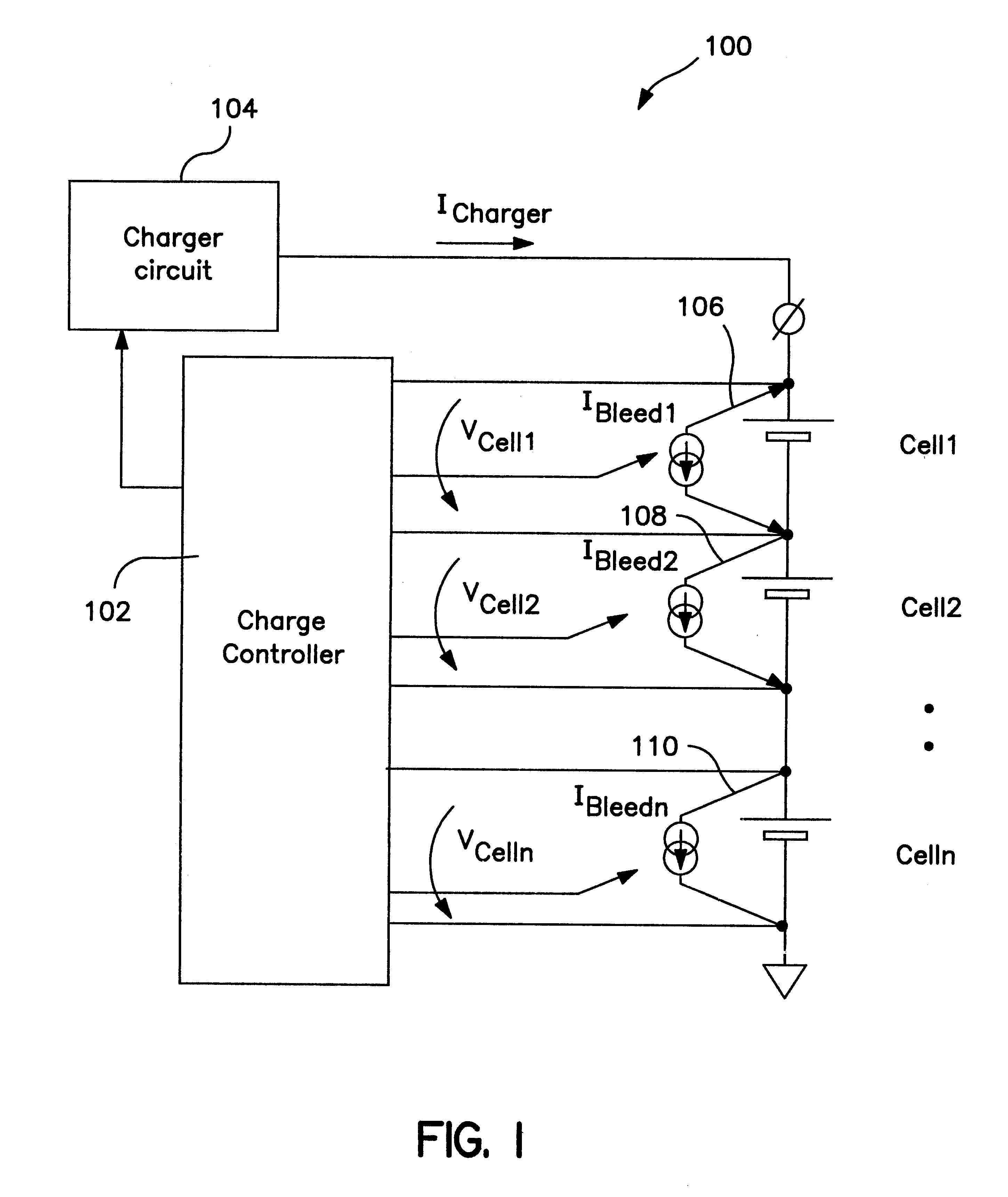
FIG. 1 is a block diagram of an exemplary cell balancing circuit of the present invention. Essentially, the cell-balancing circuit 100 operates to control the charge distribution among non-identical cells in a battery pack during the charge process. The circuit monitors the voltage of each individual battery cell, Cell1, Cell2 . . . Celln, that are connected in series within the battery, and adjusts the amount of charging current based on the cell voltage. The cells in a battery pack typically present a certain degree of charge capacity imbalance. Therefore, in conventional charging systems, the cells with a lower capacity will be charged faster than those with a larger capacity. In such a condition, there is no way to achieve 100% charging for all the cells in the battery, since either the larger capacity cells will remain undercharged, thereby reducing the effective capacity of the battery, or the lower capacity cells will be overcharged, with detrimental effects on long-term cell...


PUM


Abstract

A balanced battery cell charging circuit is provided. The circuit includes a comparator for comparing the voltage of a battery cell to a predetermined threshold voltage. If the cell voltage exceeds the threshold value, a bleeder current is generated. In one preferred embodiment, the bleeder current is subtracted from the charging current. In another embodiment, the bleeder current is multiplied, and the multiplied bleeder current is subtracted from a total charging current supplied to the cell. To control the charger circuit, current feedback is provided by monitoring the bleeder current generated against a maximum bleeder current, and adjusting the charging current accordingly. The topology of the present invention provides active cell balancing between cells of a battery, and low total power dissipation of the circuit.

Description

1. Field of the InventionThe present invention relates to a balanced battery cell charging circuit. More particularly, the present invention relates to a battery charging circuit that monitors the voltage of each cell within the battery, and supplies a charging current depending on the cell voltage. Particular utility of the present invention is a battery charging circuit for portable electronic devices; although the present invention has utility in any system that uses rechargeable batteries.2. Description of Related ArtVarious charger circuits and techniques for charging and recharging secondary cells are known. In one such technique, the cell voltage is monitored and a charge current supplied to the cell is reduced as the cell voltage increases. This technique is based on a recognition that, as the voltage across the cell increases, its charge acceptance decreases. Other battery charging techniques utilize circuitry for sensing the charge accepted by the cell and reducing the cha...

Claims


Application Information

Patent Timeline
IPC IPC(8): H01M10/42H01M10/44H02J7/00
CPCH02J7/0016H01M10/44Y02E60/10
Inventor POPESCU, SERBAN-MIHAI
Owner O2 MICRO INT LTD
Why Eureka
Try Eureka