

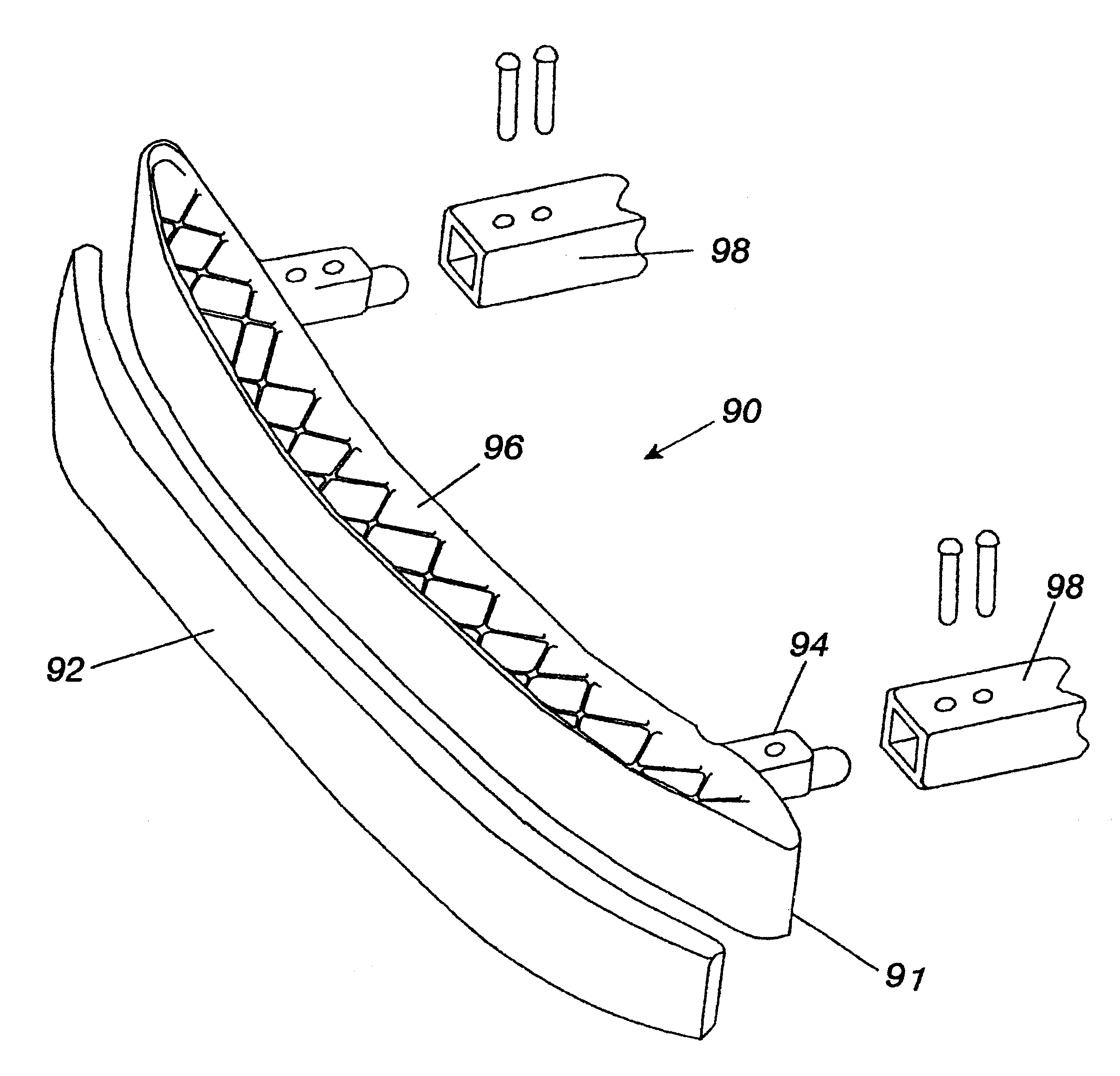
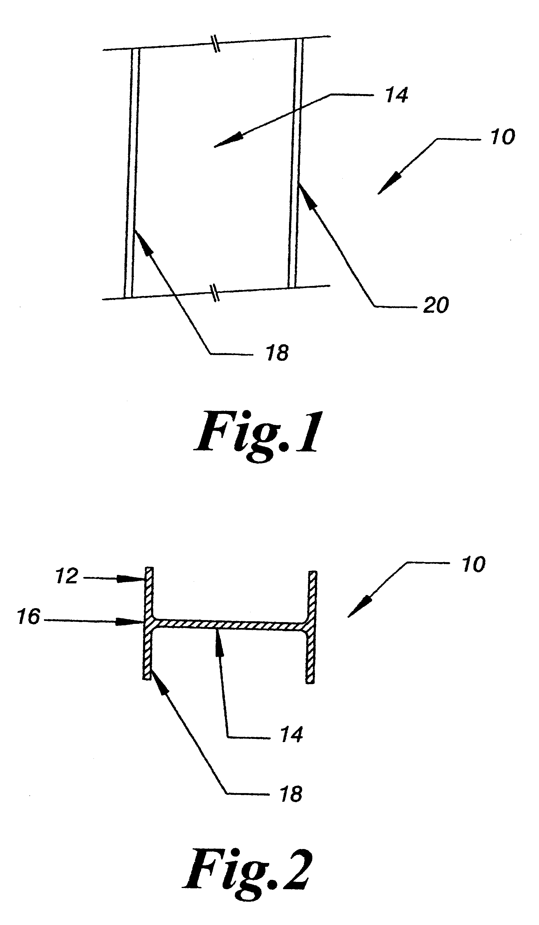
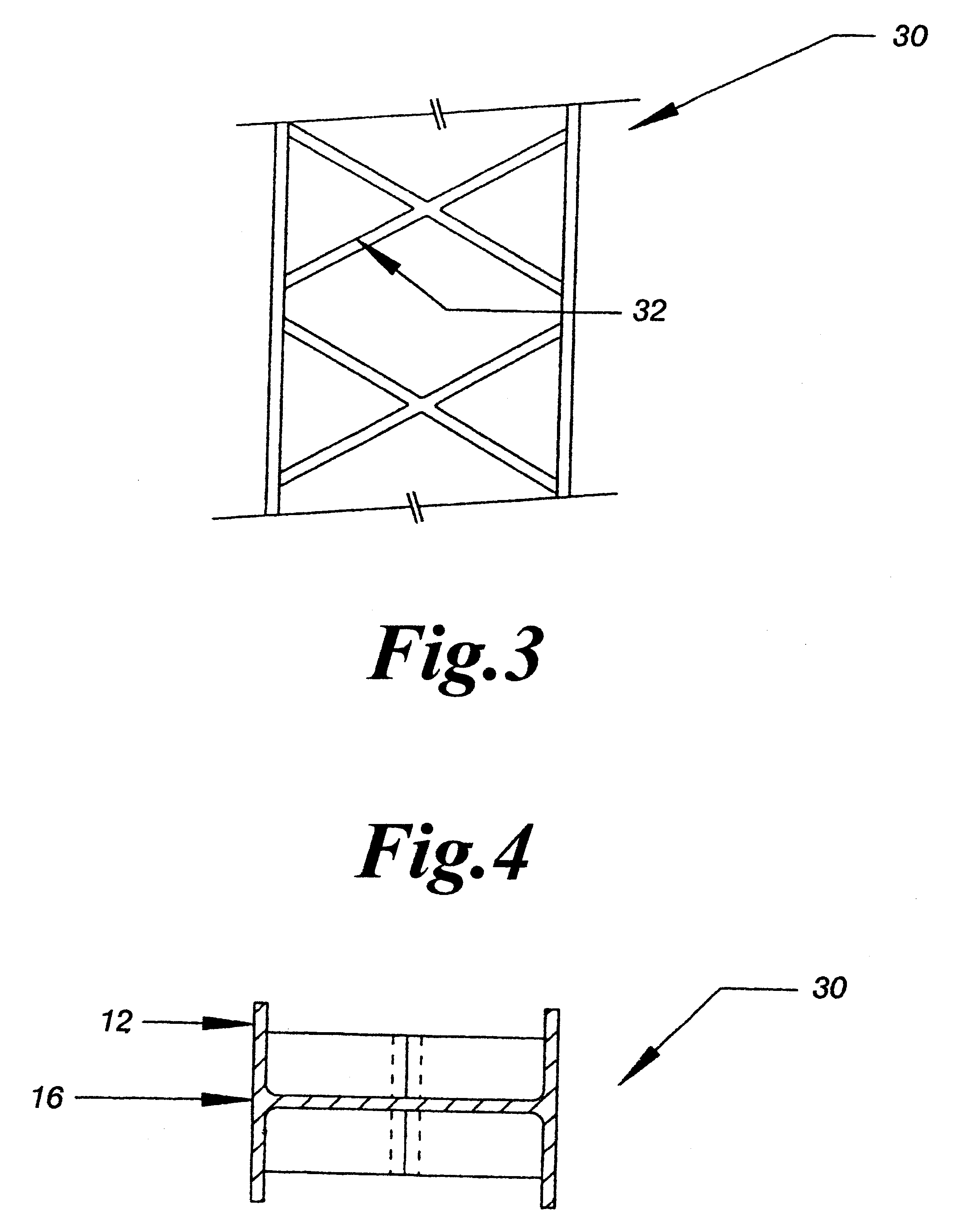
I-Section automotive bumper formed from mineral-filled glass mat thermoplastic (GMT) composite
a technology of thermoplastics and composites, applied in the direction of bumpers, vehicle components, vehicular safety arrangements, etc., can solve the problems of increasing the weight of automobiles, increasing fuel efficiency, and high cost of metal bumper components, and achieves favorable flow characteristics, improved modulus or cross-face stiffness of finished parts, and more costly fibers
- Summary
- Abstract
- Description
- Claims
- Application Information
AI Technical Summary
Benefits of technology
Problems solved by technology
Method used
Image

Examples
example a
Bumper beams were tested using a Pendulum Bumper Test. Two test configurations were used, FMVSS Barrier and Pole. Data was accumulated for 4 beams each of 6 different materials.
All the products tested yielded good results in the Barrier loads, with no beam breakage. The GMT (A & B) materials were standard, commercially available products from two different manufacturers. Their performance was acceptable and was used as the "control" group for experimental analyses. Improved formulations, 40% LF GMT products, were tested, but showed only marginal improvements over the "control" groups. The 45-46% Mineral Filled GMT experiments demonstrated the highest Barrier and Pole Peak Loads and lowest intrusion. Only the mineral filled GMT formulations produced a beam that had little or no breaks in the Pole test. The combination of long fiber glass and small, plate-like mineral particles easily flow into all the areas of the I-Section bumper beams. This homogeneous composition is able to optimi...
example b
The design and manufacturing process proceeds through three stages of computer-aided engineering (CAE) and finishes with prototype tooling and parts for physical testing. The CAE process includes computer simulation of the response to the Federal Motor Vehicle Safety Standard 581 and the Insurance Institute for Highway safety 8.0 kph Rear Pole Impact requirements. The simulation results correlate well with the physical testing discussed in Example A hereinabove.
Referring to FIG. 7, FIG. 7 shows the beam sections whose dimensions are determined using the CAE protocol of this invention. The first phase of the CAE process is to enter the known parameters of the design, such as vehicle dimensions, weight and so forth. The starting point is a computer representation of twenty I-beam segments 40. The sections are modeled from the centerline of the bumper 42 to the rail support 44. The sizes for the sections vary uniformly from the centerline to the rail support 44.
Four variables are optim...
PUM
 Abstract
Description
Claims
Application Information