
Downhole tool data correction method and apparatus

a technology of data correction and downhole tool, which is applied in the field of subsurface earth formation investigation, can solve the problems of spectral degradation, general deformation of spectral peaks that are relatively "sharp" and well defined at room temperature, and not all gamma ray detectors will have the same inherent or so-called "intrinsic" resolution

Inactive Publication Date: 2001-09-11
SCHLUMBERGER TECH CORP
View PDF10 Cites 36 Cited by
  • Summary
  • Abstract
  • Description
  • Claims
  • Application Information

AI Technical Summary

Problems solved by technology

These scintillation detectors typically all have the undesirable characteristic of losing pulse-height resolution with increasing temperature, resulting in spectral degradation.
This means that spectral peaks that are relatively "sharp" and well defined at room temperature will generally degrade (broaden) when the detector gets hot.
In addition, not all gamma ray detectors will have the same inherent or so-called "intrinsic" resolution even at room temperature.
As a scintillation detector heats up, the detector resolution typically worsens and the carbon and oxygen peaks broaden, resulting in a net "spillover" or loss of counts from both the carbon and oxygen windows.
Unfortunately, the carbon window 130 and oxygen window 170 count-rates do not both change by the same percentage, and this results in a net bias in the windows COR value.
Typically, the windows COR value generally tends to increase with worsening resolution.
Consequently, the measured windows COR value of a given tool will generally give an erroneous oil-saturation reading when hot.
In addition, a tool having a worse intrinsic resolution than the tool used in the laboratory or database characterizations will also give an erroneous oil-saturation reading, even at room temperature.
This error is due solely to detector resolution degradation, since all other formation / borehole parameters were held constant.

Method used


Image

  • Downhole tool data correction method and apparatus

Examples


Embodiment Construction

In the interest of clarity, not all features of actual implementation are described in this specification. It will be appreciated that although the development of any such actual implementation might be complex and time-consuming, it would nevertheless be a routine undertaking for those of ordinary skill in the art having the benefit of this disclosure.

The data correction techniques disclosed herein are applicable to gamma ray data, obtained with conventional downhole tools, such as those disclosed in the referenced '446 patent. Generally, these types of downhole tools are used for evaluating cased borehole formations to determine the remaining hydrocarbon saturation in the formation, with the capability of providing additional measurements of the fluid phases within the borehole.

FIG. 5 illustrates one particular embodiment of a method 500 practiced in accordance with the present invention. FIG. 6 illustrates one particular apparatus 600 with which the method 500 may be practiced. F...


PUM


Abstract

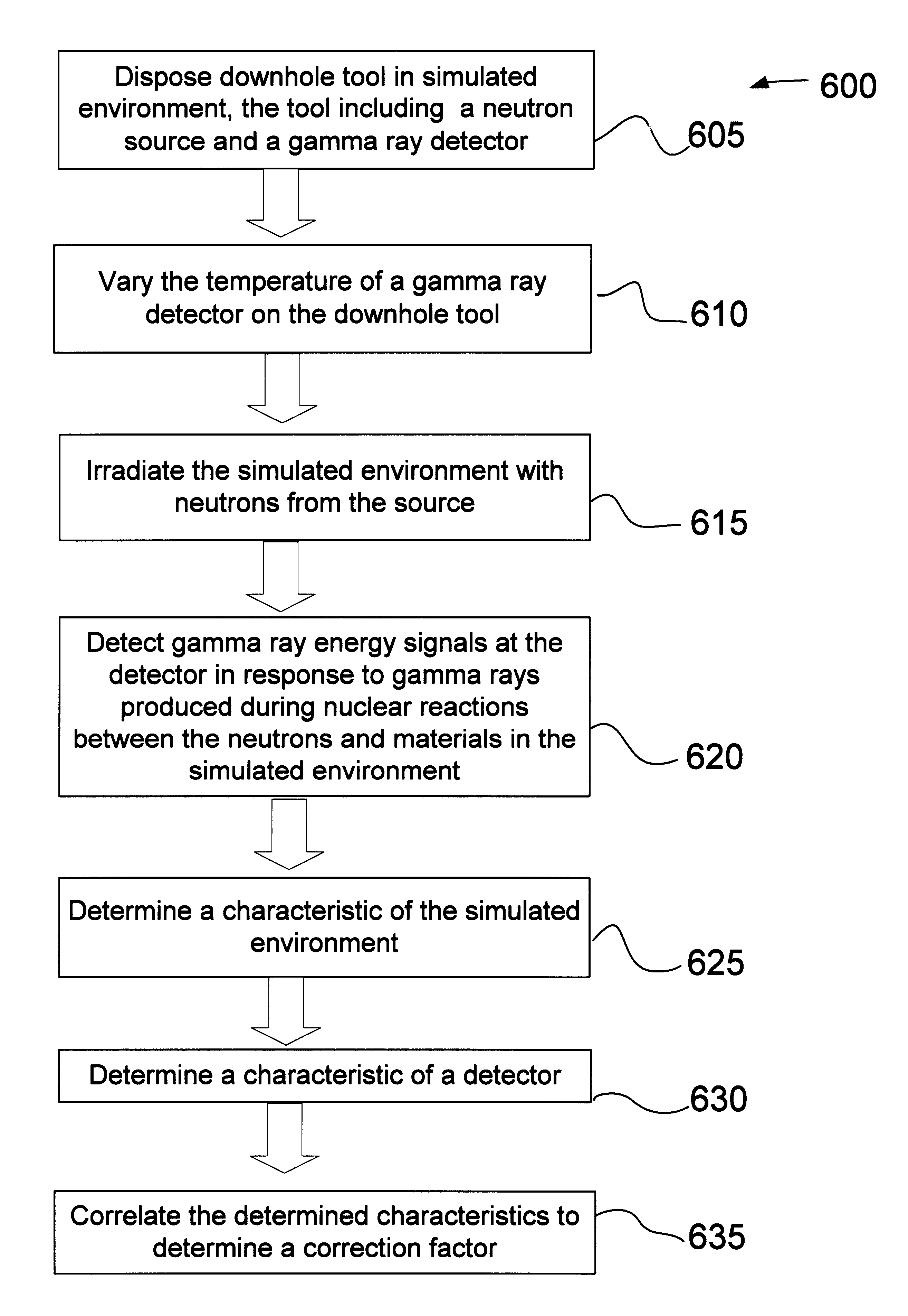
A method and apparatus are provided for correcting gamma ray data representative of gamma ray energies for spectral degradation. The method and apparatus include degrading reference gamma ray spectra. At least one correction factor is calculated between the degraded gamma ray spectra and the reference gamma ray spectra. The gamma ray data are then corrected using a calculated correction factor. Another method is provided for determining a correction factor for correcting data representative of gamma ray energies for spectral degradation. The method includes disposing a downhole tool in a simulated environment representative of actual downhole conditions, the tool including a neutron source and at least one gamma ray detector. The temperature of at least one of the gamma ray detectors of the tool is then varied while the simulated environment is irradiated with neutrons emitted from the neutron source. Gamma ray energy signals are then detected at the at least one detector in response to gamma rays produced during nuclear reactions between the neutrons and materials in and of the simulated environment. A characteristic of the simulated environment is then determined along with a characteristic of the at least one detector. The determined characteristics of the simulated environment and of the at least one detector are then correlated to determine at least one correction factor.

Description

1. Field of the InventionThis invention relates generally to investigation of subsurface earth formations, and, more particularly, to a method for correcting data obtained by a downhole tool for anomalies that may be caused by factors including environmental characteristics and / or intrinsic tool parameters. The invention has general application in the well logging art, but is particularly useful at a well site while logging.2. Description of Related ArtA major goal of well logging is to maximize the amount of hydrocarbons recovered from an earth formation. By continuously monitoring oil saturation in the earth formation, secondary and tertiary techniques may be employed to enhance recovery of hydrocarbons. Oil saturation is usually expressed as a percentage by volume of oil in the pore space. Different methods have been developed for monitoring oil saturation during production of a well.One method for monitoring oil saturation is based on the fact that hydrocarbons contain carbon an...

Claims


Application Information

Patent Timeline
IPC IPC(8): G01V5/10G01V5/00
CPCG01V5/101
Inventor PLASEK, RONALD E.
Owner SCHLUMBERGER TECH CORP
Learn More