Thermoelectronic generating electronic device

a technology of electronic devices and thermoelectric generators, which is applied in the direction of electric windings, instruments, horology, etc., can solve the problems of limited earth resources, periodic exchange, and thermal conductivity problems of thermoelectric generating electronic devices

Inactive Publication Date: 2001-09-18
SEIKO INSTR INC
View PDF6 Cites 29 Cited by
  • Summary
  • Abstract
  • Description
  • Claims
  • Application Information

AI Technical Summary

Problems solved by technology

However, these batteries are articles of consumption so that periodic exchange is required and limited resources of the earth are consumed.
However, the conventional thermoelectric generating electronic device has problems in thermal conductivity from the high temperature portion to a heat receiving portion of a thermoelectric generator, thermal conductivity from a heat radiating portion of the thermoelectric generator to the low temperature portion, etc.
Further, a problem exists in that the above temperature difference sufficient to generate required electric energy by the thermoelectric generator cannot be obtained.
Therefore, the temperature difference between the heat receiving portion and the heat radiating portion of the thermoelectric generator is large.
Therefore, a problem exists in that no thermoelectric generator can almost generate electric energy.
However, no counter electromotive force is utilized since there is no large effect in consideration of electric power consumed for this means.
However, resistance is large in the heat radiation to the air so that the heat radiation is gradually saturated.
Further, when the above thermoelectric generating electronic device is stored in a state in which no thermoelectric generating electronic device is mounted to the arm, there is a change in room temperature if the thermoelectric generating electronic device is left in an environment in which no heat is insulated.
However, a time difference is caused in the temperature change by arranging the heat accumulating material so that a temperature difference is caused.

Method used


Image

  • Thermoelectronic generating electronic device
  • Thermoelectronic generating electronic device
  • Thermoelectronic generating electronic device

Examples


first embodiment

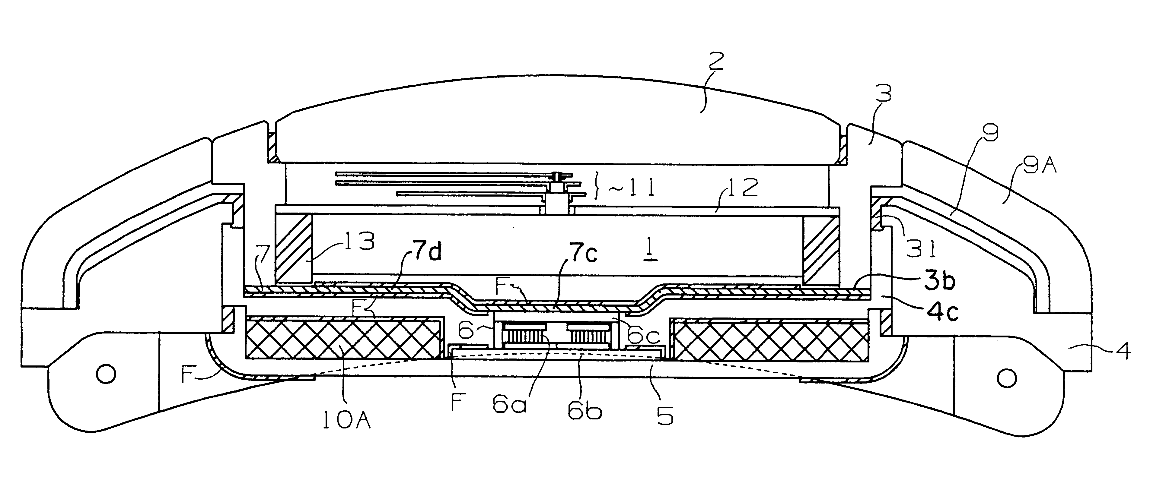
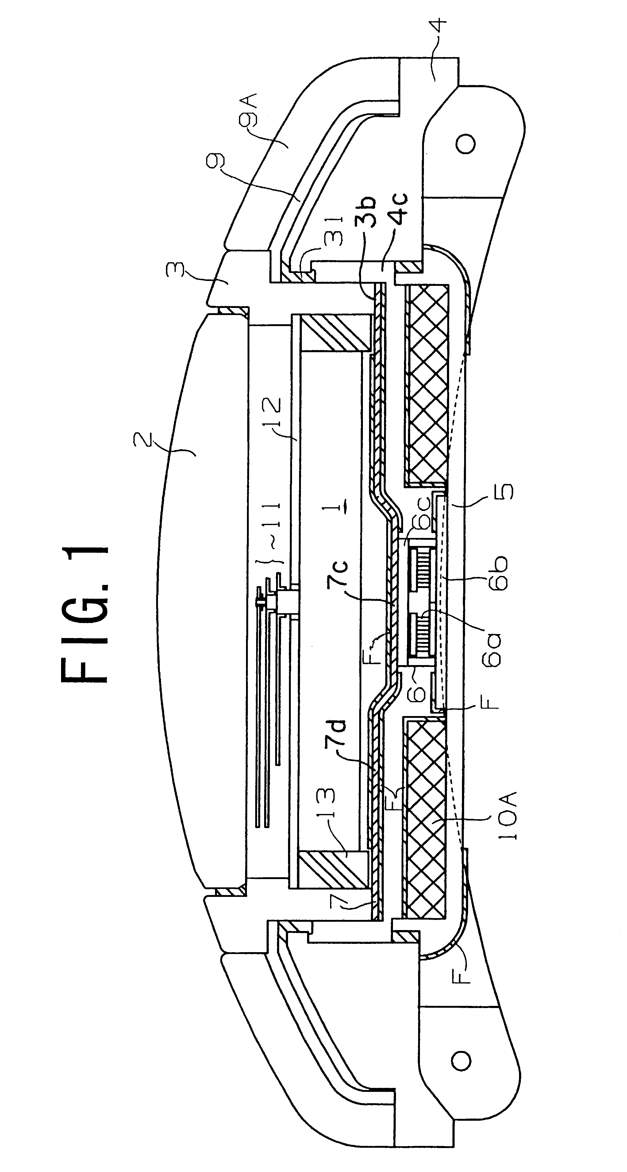
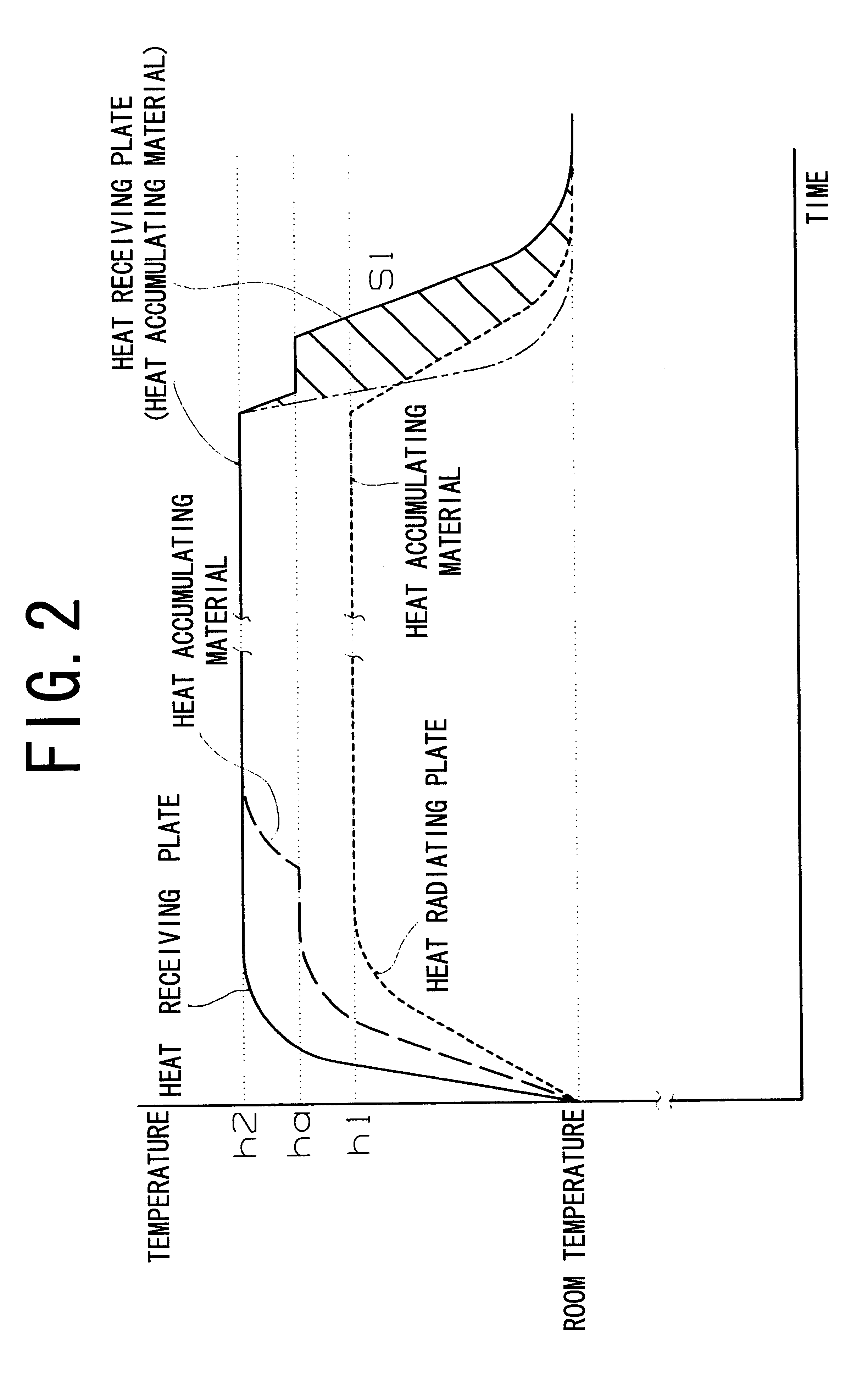
FIG. 1 is a cross-sectional view of a wrist watch illustrated as a first embodiment mode example of the thermoelectric generating electronic device in the present invention. FIG. 2 is a graph showing changes in temperatures of a heat radiating portion and a heat receiving portion of a thermoelectric generator arranged in the wrist watch of FIG. 1.

In FIG. 1, reference numeral 1 denotes a movement; 2, a glass; 3, a bezel; 4, a first frame or heat insulating drum comprise of a heat insulating material; 5, a rear cover; 6, a thermoelectric generator; 7, a heat conducting plate; 9, a second frame or heat radiating drum for radiating heat; 10A, a heat accumulating material (a first heat accumulating material); 11, a hand; 12, a character board; 13, a middle frame; 31, a packing; F, a heat insulating material; and 9A, a heat radiating fin.

The thermoelectric generator 6 is constructed by plural (e.g., twelve) thermoelectricity generating elements 6a- - - , and a heat radiating portion 6c an...

second embodiment mode example

FIG. 3 is a cross-sectional view of a wrist watch illustrated as a second embodiment mode example of the thermoelectric generating electronic device in the present invention. FIG. 4 is a graph showing changes in temperatures of a heat radiating portion and a heat receiving portion of a thermoelectric generator arranged in the wrist watch of FIG. 3.

In this embodiment mode, a heat accumulating material 10B is arranged on a side of the heat radiating portion 6c of the thermoelectric generator 6 as shown in FIG. 3.

In this second embodiment mode, the same portions as the above first embodiment mode are designated by the same reference numerals, and an explanation of these portions is omitted here.

In this embodiment mode, the heat accumulating material 10B (a second heat accumulating material) is fixedly attached to a face of a circumferential edge portion 7d of a heat conducting plate 7 on the side of a rear cover 5 as shown in FIG. 3.

A melting point of a substance constituting this heat...

third embodiment mode example

FIG. 5 is a cross-sectional view of a wrist watch illustrated as a third embodiment mode example of the thermoelectric generating electronic device in the present invention. FIG. 6 is a graph showing changes in temperatures of a heat radiating portion and a heat receiving portion of a thermoelectric generator arranged in the wrist watch of FIG. 5.

In this embodiment mode, a first heat accumulating material 10A is arranged on a side of the heat receiving portion 6b of the thermoelectric generator 6, and a second heat accumulating material 10B is arranged on a side of the heat radiating portion 6c of the thermoelectric generator 6 as shown in FIG. 5.

In this third embodiment mode, the same portions as the above first and second embodiment modes are designated by the same reference numerals and an explanation of these portions is omitted here.

In this embodiment mode, the heat accumulating material 10A is fixedly attached to a circumferential edge portion of the inner face of a rear cover...


PUM


Abstract

A thermoelectric generating electronic device has a heat insulating drum with a hollow portion extending in a vertical direction, a rear cover covering a lower end side of the hollow portion, a glass on an upper end side of the hollow portion, a bezel connected to the heat insulating drum, and a heat radiating drum thermally connected with the bezel. A thermoelectric generator has a heat receiving portion and a heat radiating portion for generating electric energy in accordance with a temperature difference between the heat receiving portion and the heat radiating portion. The heat radiating portion is thermally connected to the bezel and the heat receiving portion is thermally connected to the rear cover. A heat accumulating material is disposed generally parallel to the thermoelectric generator for accumulating heat and in the hollow portion, so that heat is conducted to the heat receiving portion.

Description

1. Field of the InventionThe present invention relates to a thermoelectric generating electronic device such as a wrist watch, etc., an electronic device such as a table clock, a wall clock, a page, etc. Having a thermoelectric generator.2. Description of the Related ArtThe main current of a thermoelectric generating electronic device, e.g., a wrist watch is now an electronic type wrist watch. A silver oxide battery, a lithium battery, etc. Are used as a power source of this electronic wrist watch.However, these batteries are articles of consumption so that periodic exchange is required and limited resources of the earth are consumed.Therefore, a wrist watch having an electricity generating mechanism therein instead of these batteries is researched.For example, a solar battery for converting optical energy, mechanical electricity generation utilizing gravitational energy, or thermoelectric generation utilizing the Seebeck effect based on a temperature difference, etc. are known as a...

Claims


Application Information

Patent Timeline
Patent Type & Authority Patents(United States)
IPC IPC(8): H01L35/00G04G19/00G04B37/18G04C10/00H01L35/30H01L35/32
CPCH01L35/00G04C10/00H10N10/00
Inventor MITAMURA, GEN
Owner SEIKO INSTR INC
Why Eureka
Try Eureka