Method of calibrating a system for detecting contact of a glide head with a recording media surface

a technology of detecting contact and detection system, which is applied in the direction of digital signal error detection/correction, instruments, recording signal processing, etc., can solve the problems of difficult to precisely control the electrical response characteristics of these devices, difficult to tighten the physical tolerances of glide heads, and errors in the transfer of information or even damage to the head

Inactive Publication Date: 2001-09-25
SEAGATE TECH LLC
View PDF15 Cites 26 Cited by
  • Summary
  • Abstract
  • Description
  • Claims
  • Application Information

AI Technical Summary

Problems solved by technology

A persisting problem with rigid magnetic memory disks is that asperities, which are essentially protrusions on the surfaces of the disks, may cause an anomaly when encountered by the head during high speed revolutions.
These asperities can cause errors in the transfer of information or even damage to the head.
Existing glide heads have inherent problems associated with them because it is difficult to precisely control the electrical response characteristics of these devices.
However, because the industry's demands for higher magnetic densities requires a lowering of the data head's flying height over the surface of the magnetic disks, it becomes more difficult to tighten the physical tolerances of glide heads and effect

Method used


Image

  • Method of calibrating a system for detecting contact of a glide head with a recording media surface
  • Method of calibrating a system for detecting contact of a glide head with a recording media surface
  • Method of calibrating a system for detecting contact of a glide head with a recording media surface

Examples


Embodiment Construction

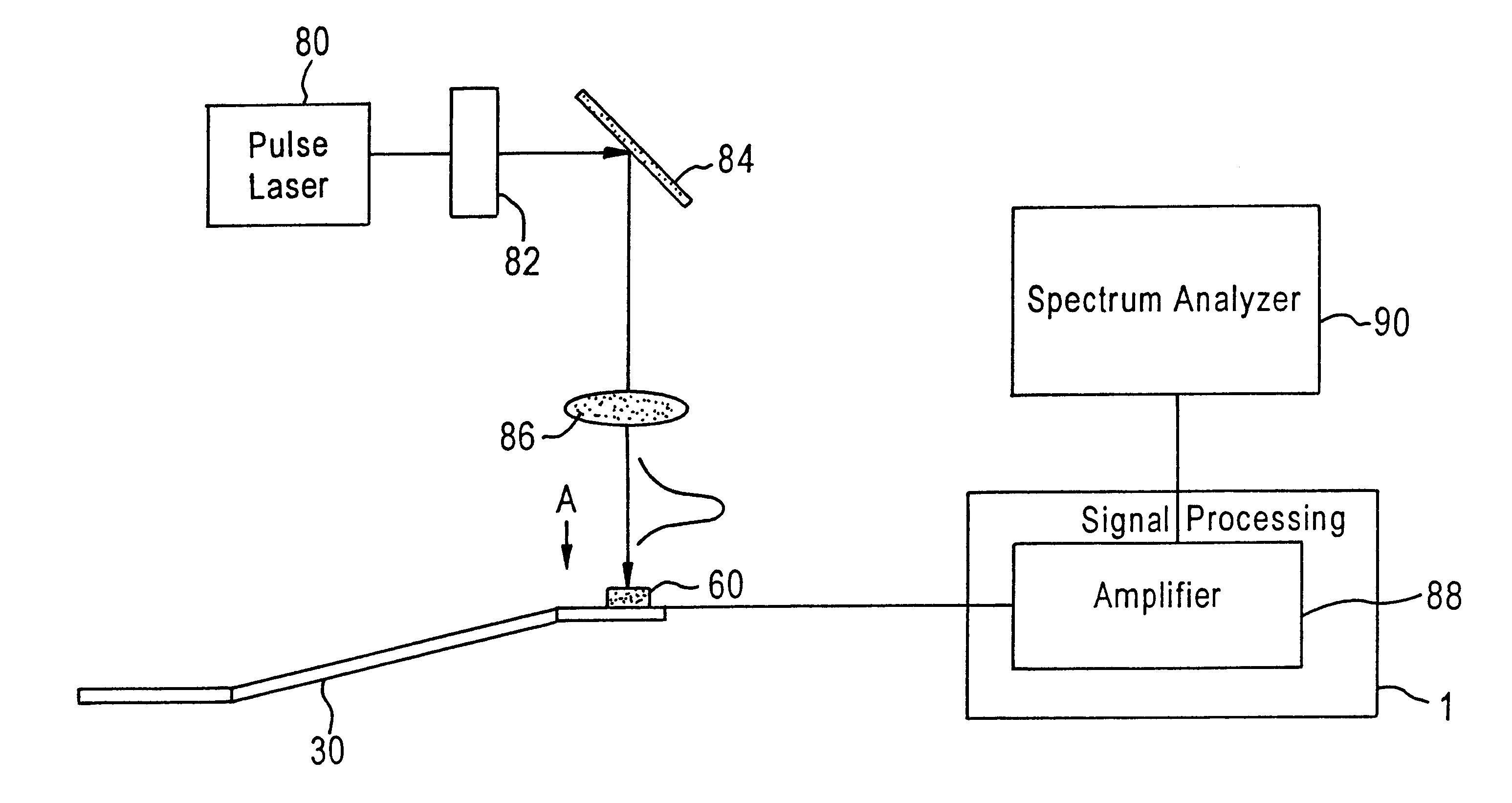
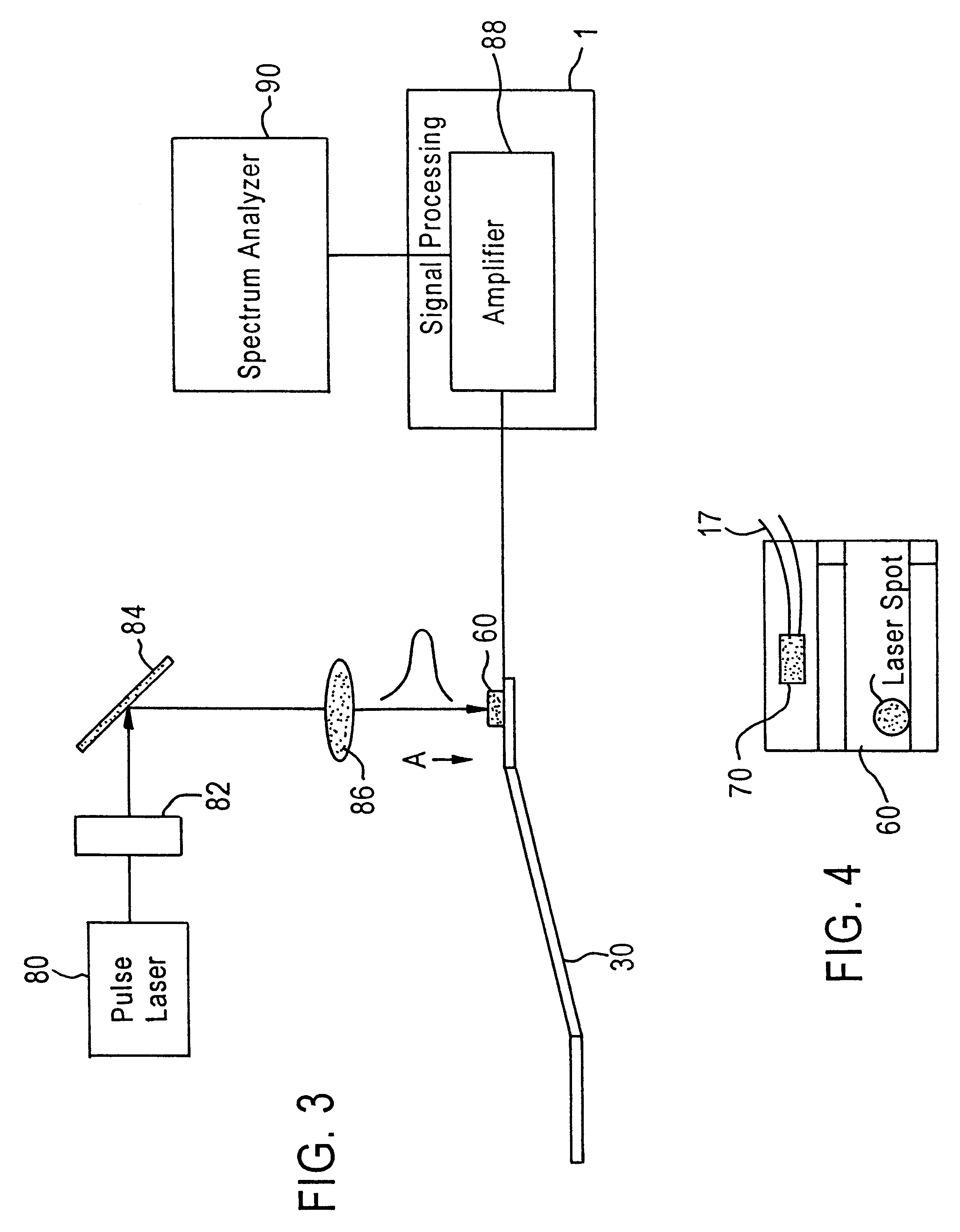
The present invention broadly relates to the calibration of a system to detect signals upon contact between a flying head and a data recording disk. Typically, current glide technology involves the use of a glide head and piezoelectric sensor that detects the signal upon head-disc contact. The traditional calibration of the detection system utilizes a specially made "bump disk" which has asperities of desired height and size that protrude out of the flat disk surface. The onset of head-disk contact, as detected by the piezoelectric sensor, defines the specific disk spinning velocity for the head to fly at the desired height. The calibration technique is affected by a number of factors, including the flying characteristics of the glide head and the quality and transfer function of the piezoelectric sensor. The present invention calibrates the glide head in a noncontact manner so that the glide head and piezoelectric sensor response can be characterized and decoupled from the calibrat...


PUM


Abstract

A method and apparatus for calibrating a glide head and detector system performs a pre-screening to ensure the quality of the glide head and the piezoelectric sensor in the detection system. The glide head and the piezoelectric sensor detect a signal when the glide head makes contact with the disk, such as a magnetic recording disk. Calibration of the detection system utilizes a specially made bump disk that has asperities of desired height and size that protrude out of a flat disk surface. The glide head is flown over the bump disk, and by gradually reducing the disk spinning velocity, the head is brought closer to the disk and eventually into contact with the asperity. The onset of contact, as detected by the piezoelectric sensor, defines a disk spinning velocity for the head to fly at the desired height. In order to decouple the glide head flying characteristics and the piezoelectric quality and transfer function from other factors that affect the calibration of the detection system, laser pulses are directed at the glide head. Head vibrations are introduced in the glide head and detected by the piezoelectric sensor. The head excitations are recorded as a spectrogram in which the resonance frequencies are observed. From the amplitude and frequency readings, head resonance frequencies are identified and the piezoelectric sensor response is characterized. This allows the pre-screening of the head/sensor system and the decoupling of the glide head flying characteristics and the piezoelectric sensor quality from the asperity integrity effects on the calibration of the detection system.

Description

This application via its continuity with 09 / 121,595, also claims priority from provisional patent application Ser. No. 60 / 057,019, filed Jul. 25, 1997, entitled NON-CONTACT GLIDE HEAD CALIBRATION WITH A PULSE LASER, which is incorporated herein by reference.1. Field of the InventionThe present invention is related to the field of glide head assemblies adapted to detect asperities which project above a specified height from moving surfaces, and more particularly, to method and apparatus for calibrating the glide head and detection system.2. Background of the InventionHard disk drives are used in most modern computer systems to store and retrieve programs and data. The hard disks are magnetic disks which are permanently enclosed in the hard disk drive to prevent contamination. Generally, the hard disk drive includes a spindle on which the disks are mounted and rotated with a selected angular velocity. The hard disk drives include a magnetic head that is translated across the surface o...

Claims


Application Information

Patent Timeline
IPC IPC(8): G01N29/24G11B33/10G11B21/21G11B33/00
CPCG01N29/2418G11B33/10G11B21/21G01N2291/014
Inventor MARCHON, BRUNO JEANKUO, DAVID SHIAO-MINYAO, WEI HSINKU, CHIAO-PING
Owner SEAGATE TECH LLC
Why Eureka
Try Eureka