

Internal combustion engine with combustion heater
a technology of combustion heater and internal combustion engine, which is applied in the direction of combustion-air/fuel-air treatment, machines/engines, lighting and heating apparatus, etc., can solve the problems of harmful gas components in burnt gas emitted from combustion heater, and low heat generation amount of internal combustion engin
- Summary
- Abstract
- Description
- Claims
- Application Information
AI Technical Summary
Benefits of technology
Problems solved by technology
Method used
Image

Examples
embodiment 1
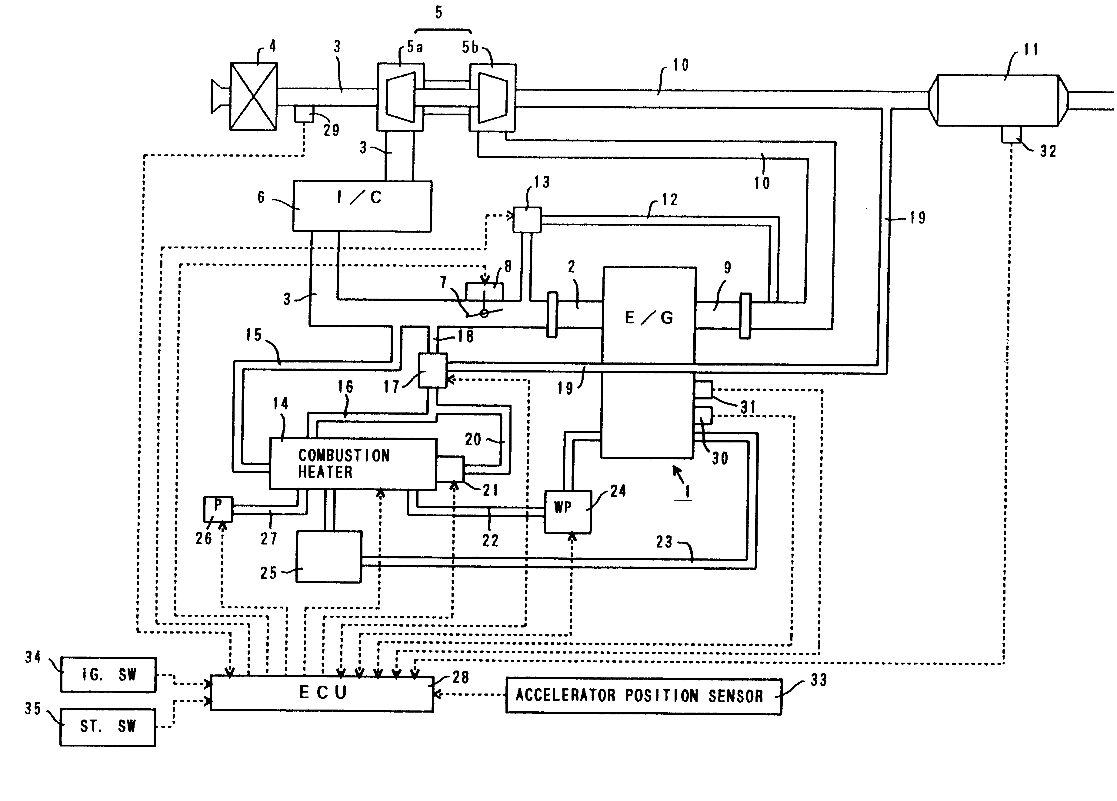
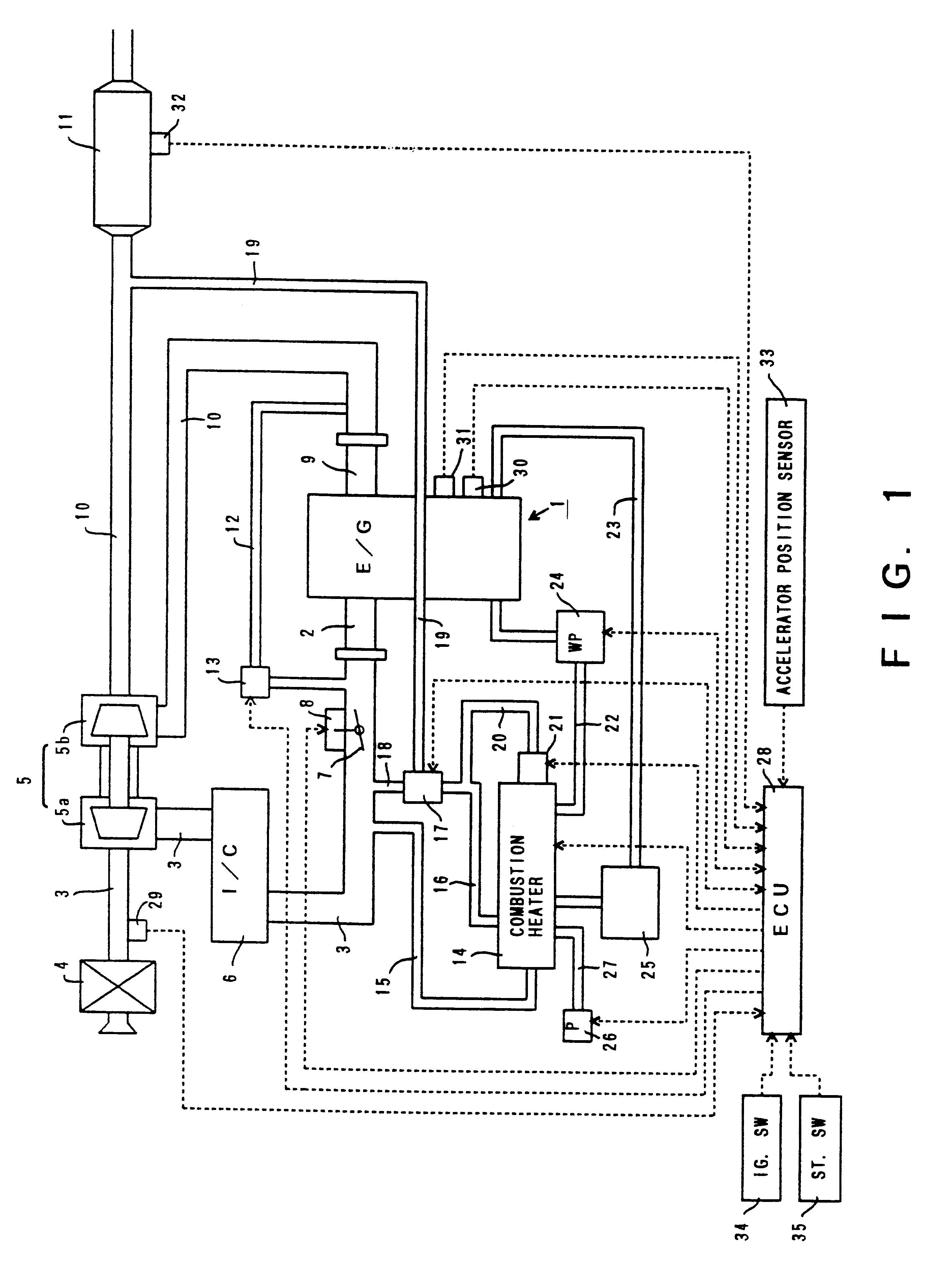
FIG. 1 is a view showing a schematic structure of an internal combustion engine with a combustion heater according to the present invention.
In FIG. 1, the internal combustion engine 1 is a water-cooled sleeve interior injection type diesel engine provided with a fuel injection valve for injecting fuel directly into a combustion chamber of each cylinder.
An intake manifold 2 is connected to the internal combustion engine 1. Each branch pipe of the intake manifold 2 is in communication with the combustion chamber of each cylinder through an intake port (not shown). The above-described intake manifold 2 is connected to an intake pipe 3. The intake pipe 3 is connected to an air cleaner box 4 containing an air filter.
A compressor housing 5a of a centrifugal supercharger (turbo charger) 5 is provided in the midway of the intake pipe 3. A compressor wheel is rotatably supported within the compressor housing 5a. A rotary shaft of this compressor wheel is connected to a rotary shaft of a turb...
embodiment 2
An internal combustion engine with a combustion heater in accordance with a second embodiment of the present invention will now be described with reference to the drawings. In this case, the structure that is different from that of the above-described first embodiment will now be described and the explanation of the similar structure will be omitted.
FIG. 9 is a schematic view of the internal combustion engine with the combustion heater in accordance with the embodiment.
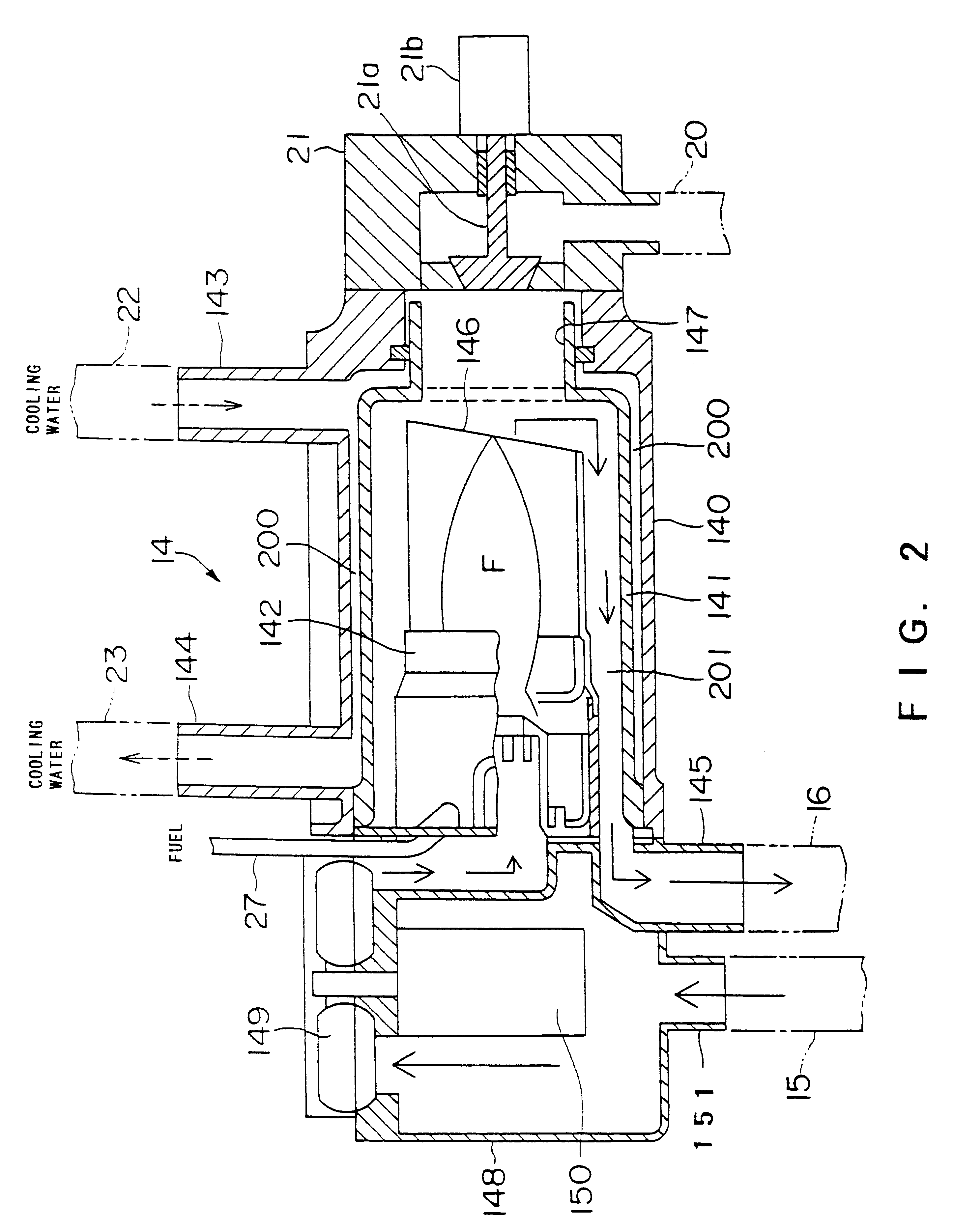
In this embodiment, the first burnt gas discharging port 145 of the combustion heater 14 is in direct communication with a portion upstream of the intake throttle valve 7 and downstream of the intake air introducing passage 15 in the intake pipe 3 through the first burnt gas discharging passage 16.
The second burnt gas discharging port 147 of the combustion heater 14 is in communication with a portion downstream of the intake throttle valve 7 in the intake pipe 3 through the valve mechanism 21 and the second burnt gas ...
embodiment 3
An internal combustion engine with a combustion heater in accordance with a third embodiment of the present invention will now be described with reference to the drawings. In this case, the structure that is different from that of the above-described first embodiment will now be described and the explanation of the similar structure will be omitted.
FIG. 10 is a schematic view of the internal combustion engine with the combustion heater in accordance with the embodiment.
In this embodiment, the first burnt gas discharging port 145 of the combustion heater 14 is in direct communication with a portion upstream of the intake throttle valve 7 and downstream of the intake air introducing passage 15 in the intake pipe 3 through the first burnt gas discharging passage 16.
The second burnt gas discharging port 147 of the combustion heater 14 is in communication with a portion downstream of the turbine housing 5b in the exhaust pipe 10 and upstream of the exhaust gas purifying catalyst 11 throu...
PUM
 Abstract
Description
Claims
Application Information