Oil-Pressure Apparatus

Inactive Publication Date: 2013-07-18
TAGUCHI INDAL
View PDF3 Cites 2 Cited by
  • Summary
  • Abstract
  • Description
  • Claims
  • Application Information

AI Technical Summary

Benefits of technology

[0019]The retraction of the rod of the actuating cylinder will now be described. Oil at a flow rate “1” is fed from the pump into the rod-side section of the actuating cylinder through the rod-side line, the third switch valve, and the second rod line. Then, oil at a flow rate “2” is discharged from the bottom-side section of the actuating cylinder. The discharged oil is fed into the bottom-side section of the acceleration cylinder through the second bottom line, the second switch valve, and the first bottom line. Then, oil at a flow rate “1” is discharged from the rod-side section of the acceleration cylinder. The discharged oil is returned to the tank through the first rod line, the first switch valve, and the bottom-side line. In this manner, while the flow rate of oil pushing the piston of the acceleration cylinder is “2”, the flow rate of oil supplied from the pump and the flow rate of oil returned to the tank are made equal at “1”. This prevents a pressure loss also when the rod of the actuating cylinder is retracted. In other wo

Problems solved by technology

However, the use of this oil-pressure apparatus reduces thrust of the rod during acceleration (FIG. 1).
Thus, the opening motion of the movable jaw is not speeded up.
Rather, oil at a flow rate “2” is discharged from the bottom-side section to cause a pressure loss in the bottom-side line, which reduces the oil suppl

Method used


Image

  • Oil-Pressure Apparatus
  • Oil-Pressure Apparatus
  • Oil-Pressure Apparatus

Examples


Example

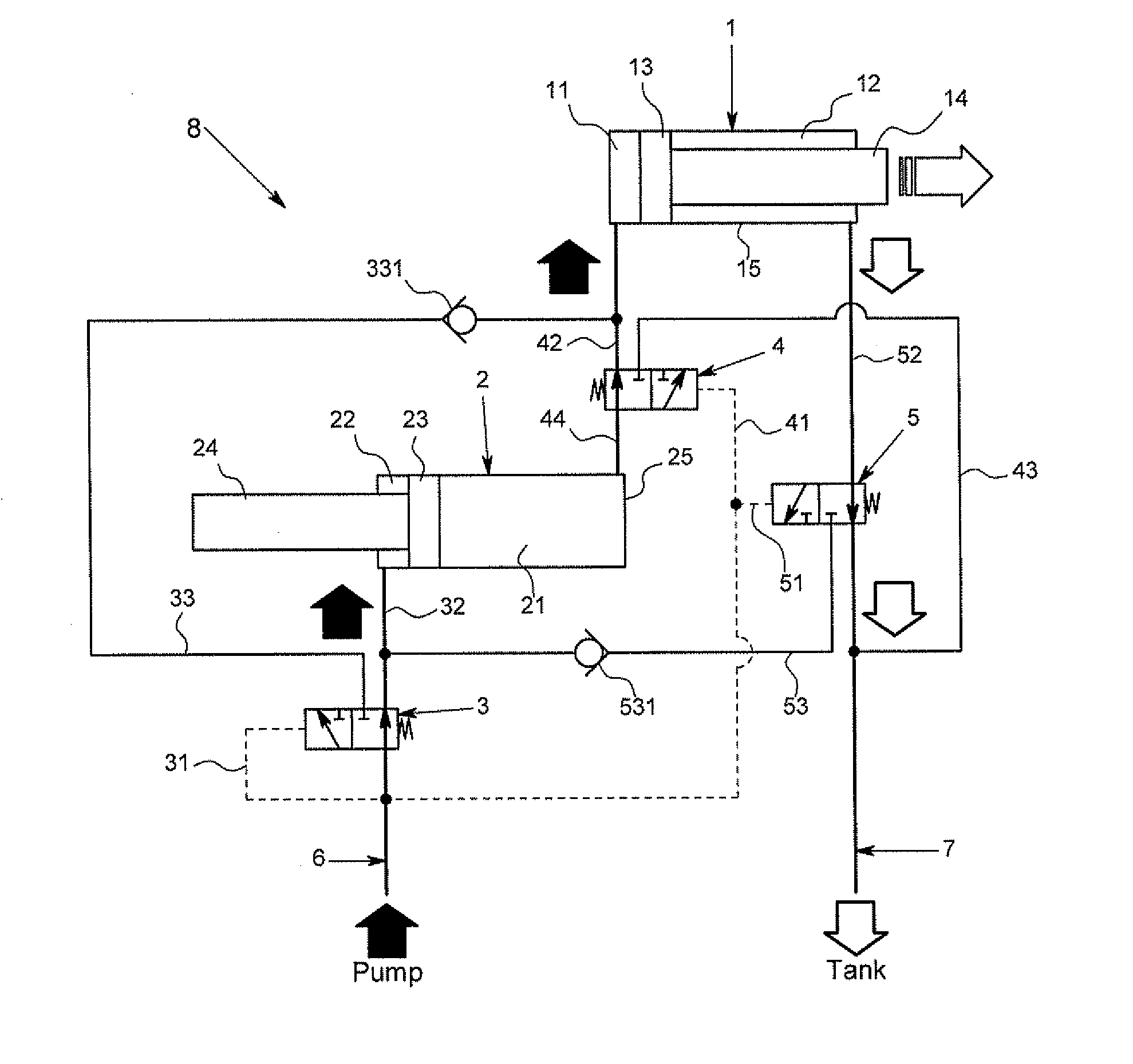
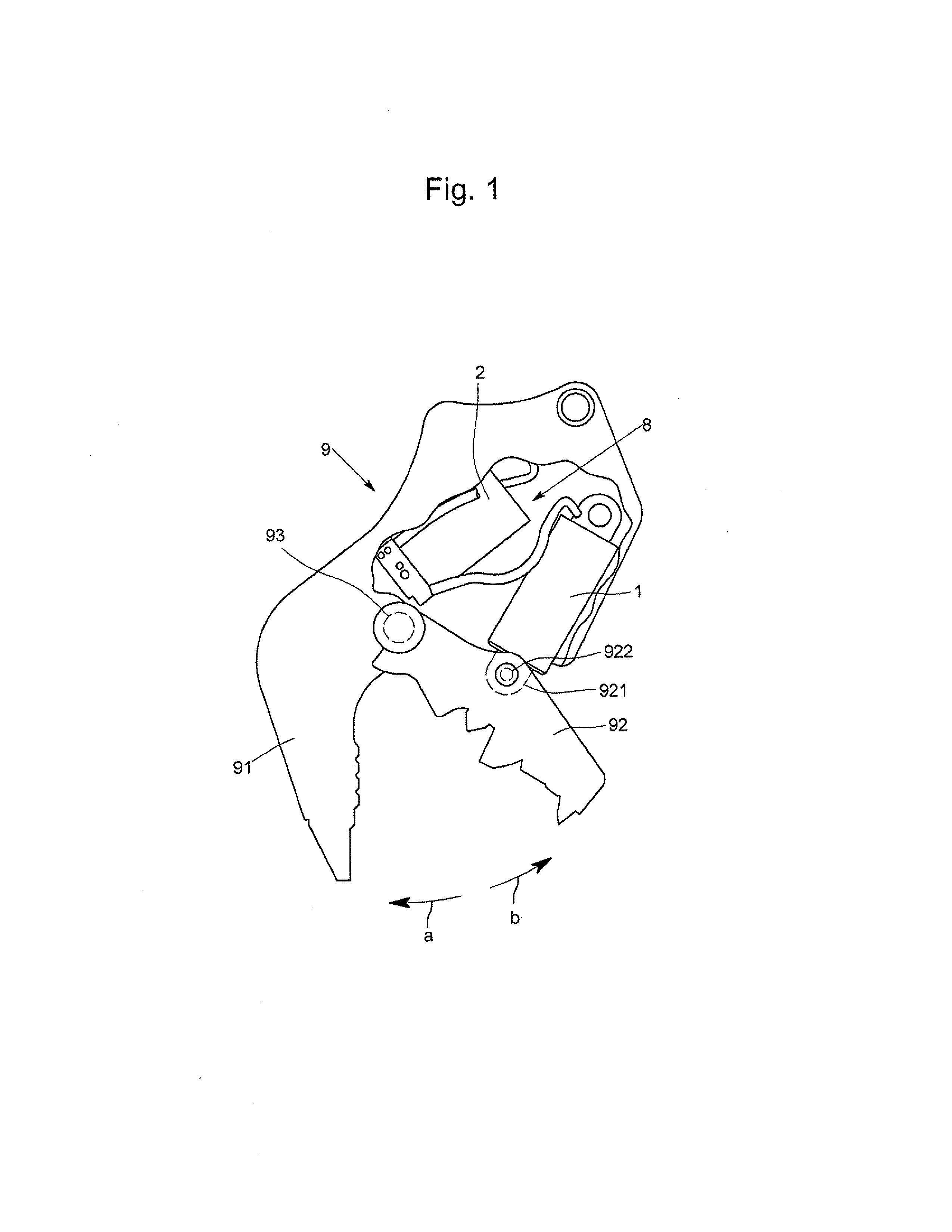
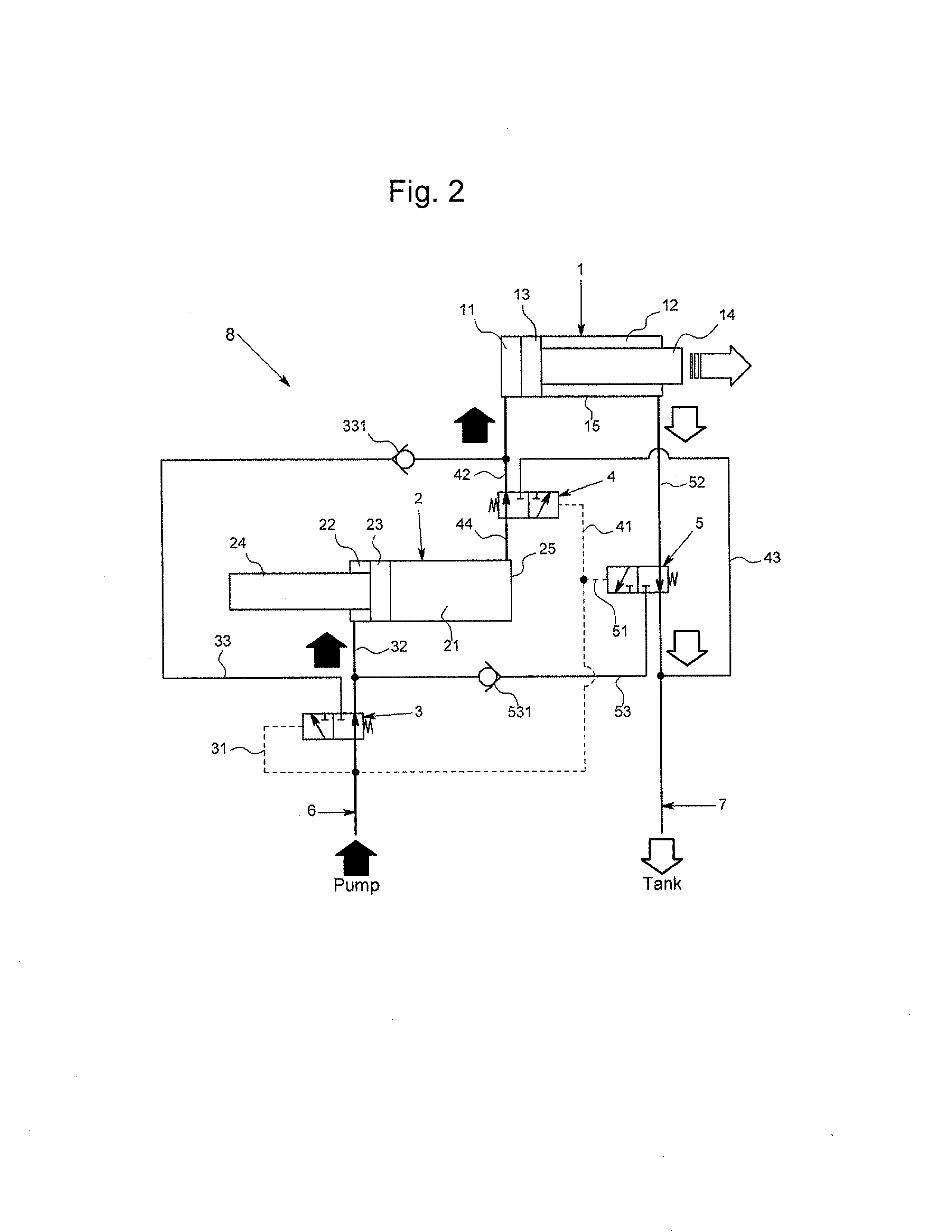
[0025]An embodiment of the present invention will be described with reference to the drawings. FIG. 1 is a schematic view of a crusher 9 with an oil-pressure apparatus 8 according to an embodiment of the present invention. For convenience of explanation, FIG. 1 shows the crusher 9 cut away to reveal an actuating cylinder 1 and an acceleration cylinder 2 which are arranged inside. The crusher 9 is an attachment attached to a main unit of construction equipment and others and actuated by the pressure of oil supplied from the main unit.

[0026]The crusher 9 includes an upper jaw 91 and a lower jaw 92. The lower jaw 92 is pivotably attached to the upper jaw 91 by means of a pivot shaft 93. The actuating cylinder 1 contains a rod. The extension / retraction of the rod moves a lower jaw support 921. The lower jaw 92 is attached to the lower jaw support 921 by means of a pivot shaft 922. The rod of the actuating cylinder 1 extends to cause the lower jaw support 921 to move integrally with the ...


PUM


Abstract

An oil-pressure apparatus is provided with an actuating cylinder that works on the outside and an acceleration cylinder that does not work on the outside. When a rod of the actuating cylinder is extended with no load applied to the actuating cylinder, oil is supplied to the actuating cylinder through the acceleration cylinder so that extension of the rod is accelerated. When the rod of the actuating cylinder is extended with load applied to the actuating cylinder, oil is adjusted to the actuating cylinder without passing through the acceleration cylinder so that original thrust of the actuating cylinder is exerted.

Description

BACKGROUND OF THE INVENTION[0001]1. Field of the Invention[0002]The present invention relates to an oil-pressure apparatus for accelerating extension or retraction of a rod of an oil-pressure cylinder.[0003]2. Description of the Related Art[0004]An oil-pressure apparatus is used, for example, for a crusher attached to a boom of a power shovel. The crusher has a movable jaw and opens / closes the movable jaw in accordance with extension / retraction of the rod of the oil-pressure cylinder.[0005]In this specification, the oil-pressure cylinder to actuate a working piece such as a movable jaw is referred to as the “actuating cylinder.” The actuating cylinder contains a piston and a rod moving integrally with the piston in a tube. The inside of the tube is partitioned into a rod-side section on the rod side and a bottom-side section on the opposite side with the piston interposed therebetween.[0006]Japanese Patent Application Publication No. 10-266587 (hereinafter referred to as JP 10-26658...

Claims


Application Information

Patent Timeline
IPC IPC(8): F15B13/06
CPCF15B13/06E02F3/965E02F9/2203F15B11/20F15B2211/783F15B2211/3057F15B2211/329F15B2211/7107F15B2211/7121F15B2211/30505
Inventor TAGUCHI, YUICHI
Owner TAGUCHI INDAL
Why Eureka
Try Eureka