Boiler

Active Publication Date: 2012-09-27
MIURA COMPANY LIMITED
View PDF5 Cites 6 Cited by
  • Summary
  • Abstract
  • Description
  • Claims
  • Application Information

AI Technical Summary

Benefits of technology

[0025]According to the invention of the fourth aspect, each of the heat-transfer tubes is divided into the first region where the relatively short fins are provided at a rough pitch, the second region where the relatively short fins are provided at a fine pitch, the third region where the relatively long fins are provided at the rough pitch, and the fourth region where the relatively long fins are provided at the fine pitch. The inner-fin absent region is provided below the first region in each of the inner heat-transfer tubes, and the outer-fin absent region is provided in the vertically middle portion of the first region in eac

Problems solved by technology

Accordingly, merely installing the fins in the same shape at equal vertical intervals in the respective water tubes without considering the above-described situation leads to an increase in heat stress occurring in the fins attached on an upstream side.
Particularly, when scale (deposit of hardness in the water) adheres to insides of the water tubes, the heat transfer from the fins to the water inside the water tubes is inhibited, thereby causing a possibility of generating excessive heat stress in the fins.
In this case, there is a possibility that the fins are overheated, thereby dropping off or burning out.
While, in view of these points, it can be considered that no fins are installed in the high-tem

Method used


Image

  • Boiler
  • Boiler
  • Boiler

Examples


Example

[0033]Hereinafter, a specific embodiment of the present invention will be described with reference to the drawings.

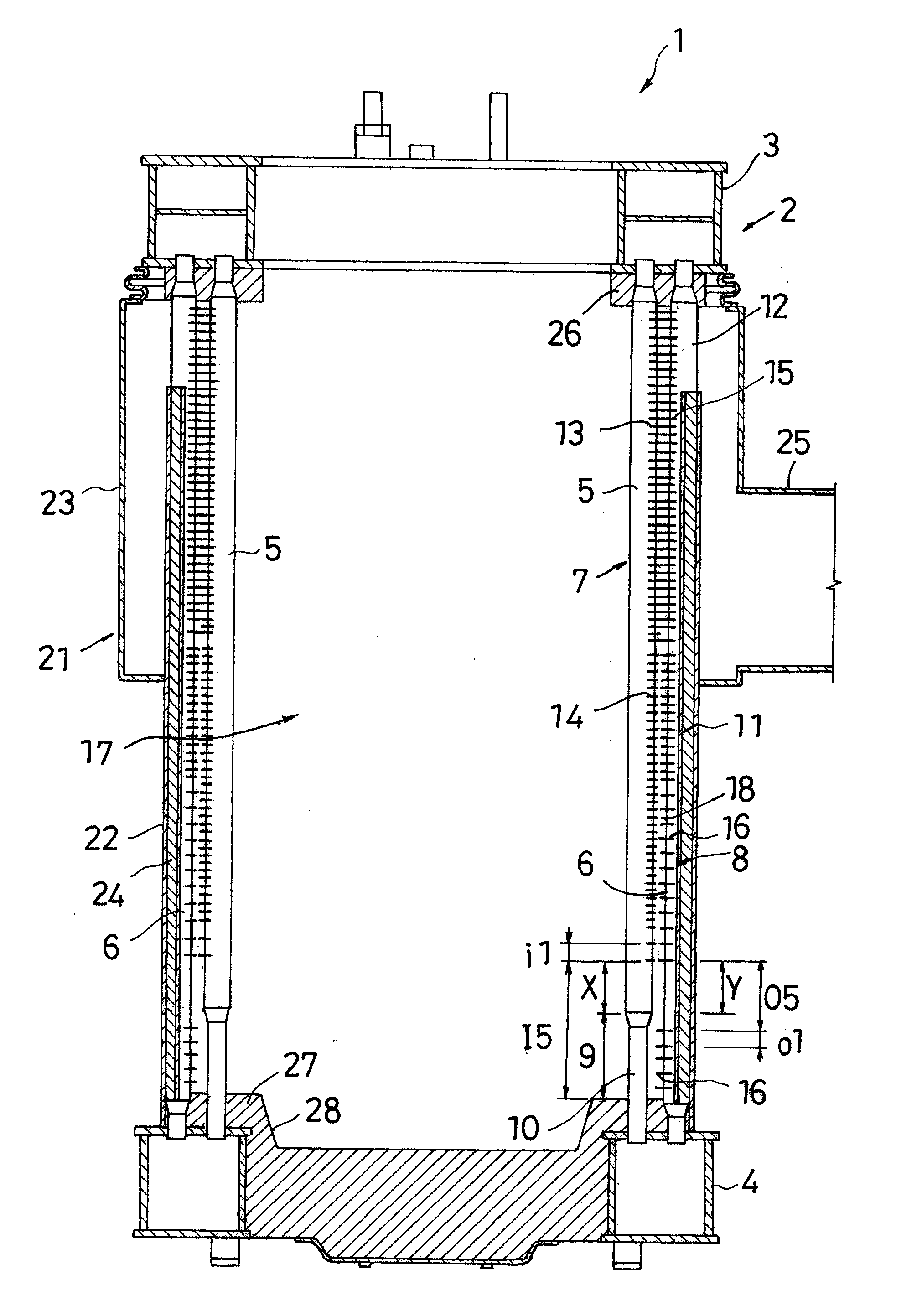
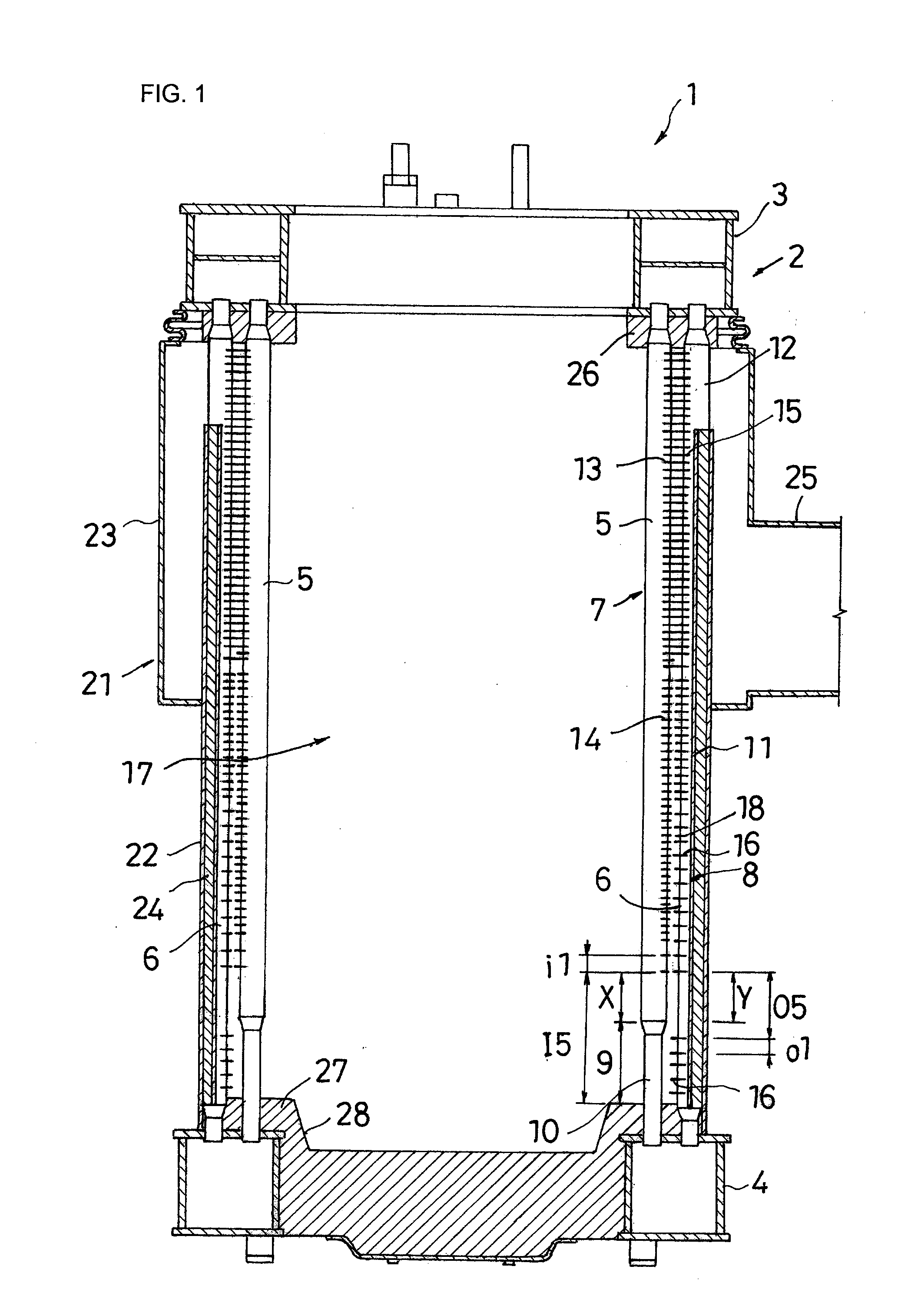
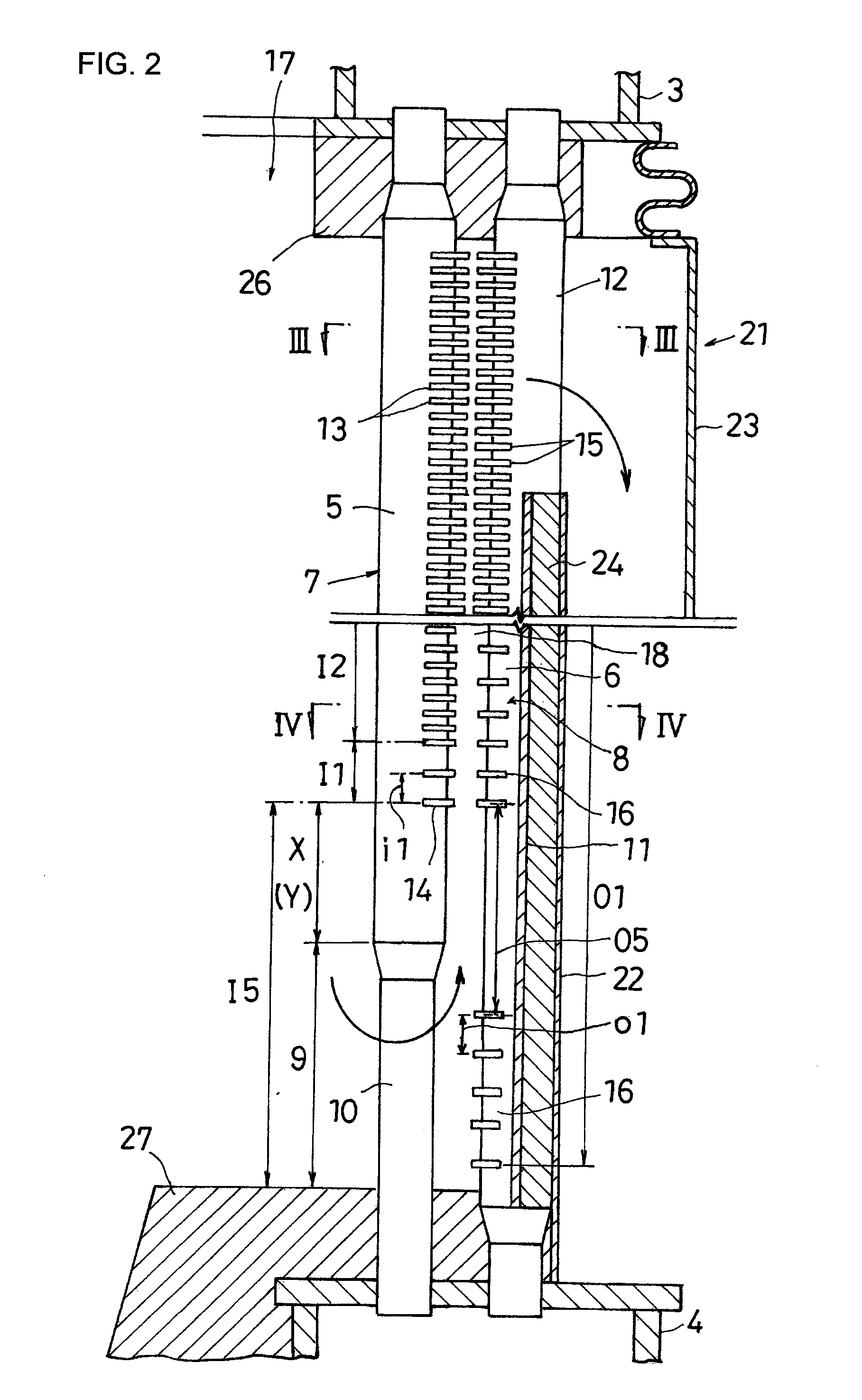
[0034]FIG. 1 is a schematic longitudinal cross-sectional view showing one embodiment of a boiler 1 of the present invention. FIG. 2 is an enlarged view of a part of FIG. 1, and FIGS. 3 and 4 are a cross-sectional view taken along and a cross-sectional view taken along IV-IV in FIG. 2, respectively.

[0035]The boiler 1 of the present embodiment is a multitubular once-through boiler including a cylindrical can body 2. The can body 2 is constructed by connecting a number of water tubes (heat-transfer tubes) 5, 5, . . . , 6, 6, . . . arrayed cylindrically between an upper header 3 and a lower header 4.

[0036]The upper header 3 and the lower header 4 are arranged in parallel at a vertical distance from each other, and are each formed into a hollow annular shape, Moreover, the upper header 3 and the lower header 4 are respectively arranged horizontally on the same axis.

[0037]The...


PUM


Abstract

A boiler has a plurality of inner heat-transfer tubes which makes up an inner heat-transfer tube row, and a plurality of outer heat-transfer tubes which makes up an outer heat-transfer tube row. Inner fins project from each of the inner heat-transfer tubes on an outer circumferential side of the inner heat-transfer tube row. Outer fins project from each of the outer heat-transfer tubes on an inner circumferential side of the outer heat-transfer tube row. An inner row communicating portion is provided in a lower end portion of the inner heat-transfer tube row. An outer row communicating portion is provided in an upper end portion of the outer heat-transfer tube row. An inner-fin absent region is provided in a lower end portion of each of the inner heat-transfer tubes. An outer-fin absent region is provided in a longitudinally middle portion of each of the outer heat-transfer tubes.

Description

BACKGROUND OF THE INVENTION[0001](1) Field of the Invention[0002]The present invention relates to various types of boilers including a steam boiler, hot-water boiler, a waste-heat boiler, and an exhaust-gas boiler.[0003](2) Description of the Related Art[0004]A boiler of a conventional multitubular boilers includes a can body constructed by arraying a number of water tubes concentrically and cylindrically between an upper header and a lower header, which are annually formed. In the above-described can body, an inside of an inner water tube row serves as a combustion chamber, and a clearance between the inner water tube row and an outer water tube row serves as a combustion gas path.[0005]Accordingly, when combustion of fuel is performed toward the combustion chamber from a burner installed in an upper portion of the can body, combustion gas reverses in a lower portion of the combustion chamber, and passes between the inner water tube row and the outer water tube row to be exhausted ...

Claims


Application Information

Patent Timeline
IPC IPC(8): F24H1/00
CPCF24H9/0026F28F1/24F28F2215/04F24H1/406F22B21/36F24H1/145F22B21/348
Inventor SUMI, SOJI
Owner MIURA COMPANY LIMITED
Why Eureka
Try Eureka