Method and device for reducing concentrations of ozone and nitric acid generated in cooling air flowing through circulating airflow paths in rotary electric machines

Active Publication Date: 2013-03-07
MITSUBISHI ELECTRIC CORP
View PDF4 Cites 0 Cited by
  • Summary
  • Abstract
  • Description
  • Claims
  • Application Information

AI Technical Summary

Benefits of technology

The present invention provides a method and device that can reduce the production of ozone and nitric acid in a rotary electric machine's cooling airflow while maintaining proper pressure. This can help to prolong the life of the machine and ensure it runs efficiently.

Problems solved by technology

However, the partial discharge may occur due to various factors such as deterioration over time of winding insulation or a partial discharge inhibitor.
As a result, metal members (for example, bolts and aluminum fins) in the generator may be corroded, or organic materials may be deteriorated.

Method used


Image

  • Method and device for reducing concentrations of ozone and nitric acid generated in cooling air flowing through circulating airflow paths in rotary electric machines
  • Method and device for reducing concentrations of ozone and nitric acid generated in cooling air flowing through circulating airflow paths in rotary electric machines
  • Method and device for reducing concentrations of ozone and nitric acid generated in cooling air flowing through circulating airflow paths in rotary electric machines

Examples


first embodiment

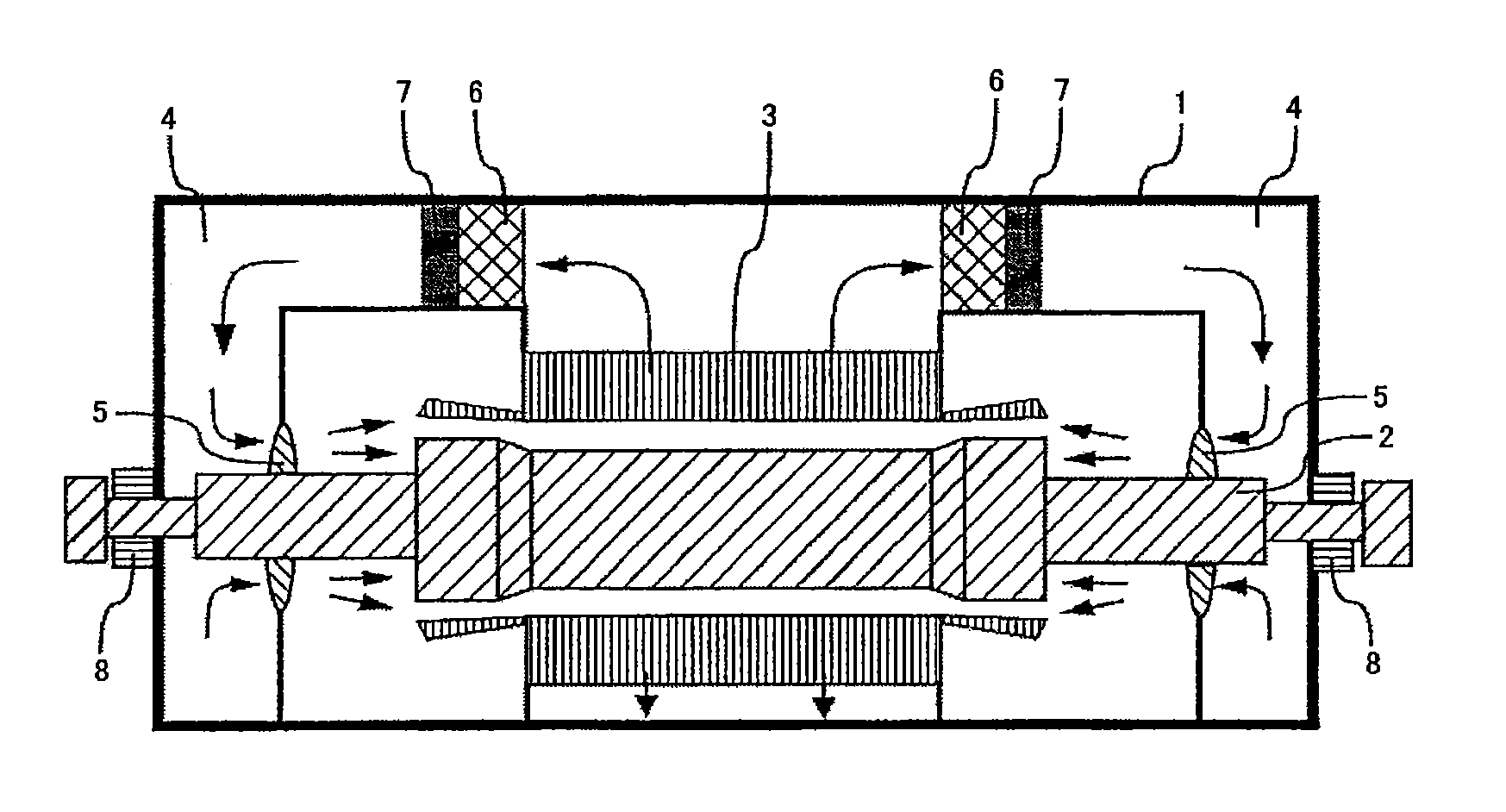
[0032]FIG. 1 is a cross-sectional view of an air-cooled turbine generator to which a method of this embodiment is applied.

[0033]In FIG. 1, the air-cooled turbine generator includes a frame 1, a rotor 2, a stator 3, a fan 5, an air cooler 6, an ozone decomposition unit 7, and bearings 8. In this air-cooled turbine generator, the rotor 2 having the fan 5 mounted thereto, the stator 3, the air cooler 6, and the ozone decomposition unit 7 are disposed in the frame 1 having a totally enclosed structure, and a rotation shaft of the rotor 2 is supported by the frame 1 with the bearings 8. In addition, a circulating airflow path 4 is formed so that cooling air sent by pressure from the fan 5 circulates around the rotor 2, the stator 3, the air cooler 6, the ozone decomposition unit 7, and the fan 5 in this order. Note that, in this air-cooled turbine generator, the ozone decomposition unit 7 is disposed on a downstream side of the air cooler 6, but the position of this ozone decomposition u...

second embodiment

[0058]FIG. 6 is a cross-sectional view of an air-cooled turbine generator to which a method of this embodiment is applied. Note that, the basic structure of the air-cooled turbine generator of this embodiment is the same as the structure of the air-cooled turbine generator of the first embodiment, and therefore the same parts are represented by the same reference numerals or symbols so that overlapping description is omitted.

[0059]In FIG. 6, the air-cooled turbine generator includes a light source 9 in the circulating airflow path 4.

[0060]In the air-cooled turbine generator of the first embodiment, the ozone decomposition unit 7 decomposes ozone produced in the cooling air flowing through the circulating airflow path 4, and hence the production of nitric acid can be suppressed. However, when a partial discharge occurs in the stator 3, a very small quantity of nitrogen trioxide (NO3) may be produced by the above-mentioned reaction (7) in a period until the cooling air exposed to the ...

third embodiment

[0065]FIG. 7 is a perspective view of the ozone decomposition unit and a nitric acid adsorption unit which are used for a method of this embodiment. In FIG. 7, the ozone decomposition unit 7 and a nitric acid adsorption unit 10 are disposed in parallel with respect to the flow of the cooling air (arrows).

[0066]In the first embodiment, production of nitric acid can be suppressed by decomposing ozone. Further, in the second embodiment, production of nitric acid can be suppressed by photodecomposition of NO3. However, when partial discharge occurs in humid air, a very small quantity of nitric acid may also be produced by the following reactions.

e+H2O→e+OH+H  (12)

NO2+OH→HNO3  (13)

[0067]In other words, when the partial discharge occurs in humid cooling air, water molecules are dissociated by electron collision so that OH is produced . Then, OH is reacted with NO2 so that nitric acid is produced . The life of OH is very short, and the reaction (13) occurs only in the vicinity of a dischar...


PUM

PropertyMeasurementUnit
Fractionaaaaaaaaaa
Fractionaaaaaaaaaa
Wavelengthaaaaaaaaaa

Abstract

The present invention provides a method for reducing concentrations of ozone and nitric acid produced in cooling air flowing through a circulating airflow path of a rotary electric machine, the method including: disposing an ozone decomposition unit containing an ozone decomposition catalyst in the circulating airflow path; and allowing the cooling air to pass through the ozone decomposition unit so as to decompose ozone and to suppress production of nitric acid. According to the present invention, the method and device are capable of reducing the concentrations of ozone and nitric acid produced in the cooling air flowing through the circulating airflow path of the rotary electric machine for a long period of time while preventing pressure loss.

Description

TECHNICAL FIELD[0001]The present invention relates to a method and a device for reducing concentrations of ozone and nitric acid produced in cooling air flowing through a circulating airflow path in a rotary electric machine using air as a cooling medium.BACKGROUND ART[0002]Rotary electric machines such as a generator or an electric motor usually have members such as a stator and a rotor. Particularly in an air-cooled turbine generator, cooling air is supplied to a circulating airflow path in the generator so that the stator, the rotor, and the like are cooled. The stator of this air-cooled turbine generator is usually formed of a core and a coil wound around the core, on which treatment for preventing partial discharge is performed. However, the partial discharge may occur due to various factors such as deterioration over time of winding insulation or a partial discharge inhibitor. Then, when the partial discharge occurs in the generator in which humid air circulates in the same ma...

Claims


Application Information

Patent Timeline
IPC IPC(8): B01D53/02B01D53/66
CPCB01D53/04B01D53/8675B01D2251/11H02K9/26B01D2257/40B01D2258/06B01D2253/102
Inventor OINUMA, GAKUWADA, NOBORUTANIMURA, YASUHIROSHIMADA, TAKAYOSHIKIBE, KATSUHIKO
Owner MITSUBISHI ELECTRIC CORP
Why Eureka
Try Eureka