Liquid distributor for packing columns

a technology of liquid distributor and packing column, which is applied in the direction of carburetor air, combustion air/fuel air treatment, separation process, etc., can solve the problems of unfavorable flow relationships in the gas flow and impaired separation effect to be achieved through material exchang

Inactive Publication Date: 2001-09-25
SULZER CHEMTECH AG
View PDF13 Cites 57 Cited by
  • Summary
  • Abstract
  • Description
  • Claims
  • Application Information

AI Technical Summary

Problems solved by technology

These large flows however present a problem: The liquid jets incident on the screens produce splashes which have a liberation of fine drops as a result.
A separation effect which is to be achieved through a material exchange is thereby impaired.
Because of the asymmetrical arrangement of the baffle walls the flow relationships in the gas flow are unfavorable at the drip edges, namely because no stable liquid films can form about the drip edges as a result of transverse flows.

Method used


Image

  • Liquid distributor for packing columns
  • Liquid distributor for packing columns
  • Liquid distributor for packing columns

Examples


Embodiment Construction

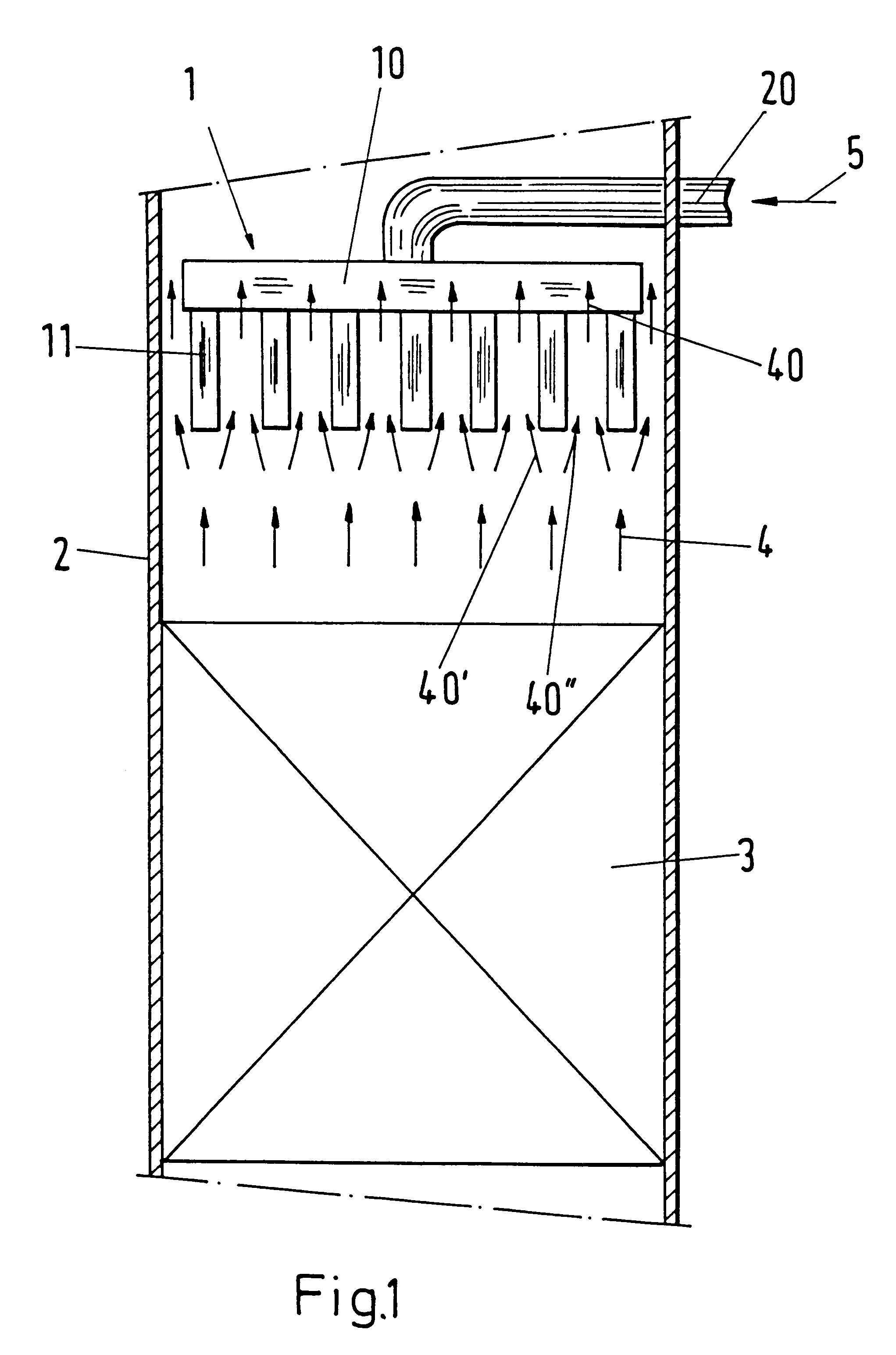
The column 2 shown in FIG. 1 contains a liquid distributor 1 and a packing 3. A gas 4 flows upwardly in the column 2, flows around distributor members 11 of the liquid distributor 1 above the packing 3 and is thereby separated into a plurality of partial flows 40', 40", which subsequently form partial flows 40. The distributor members 11 receive a liquid 5 to be distributed via a supply line 20 and a pre-distributor 10.

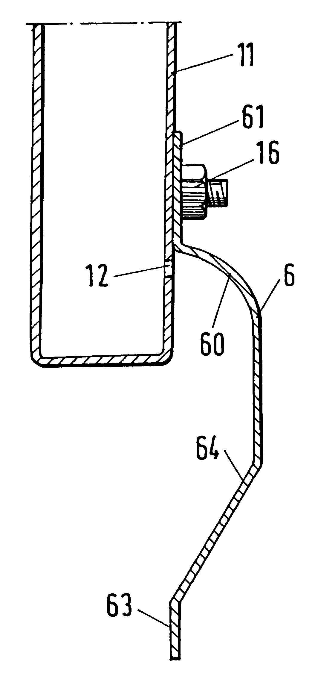
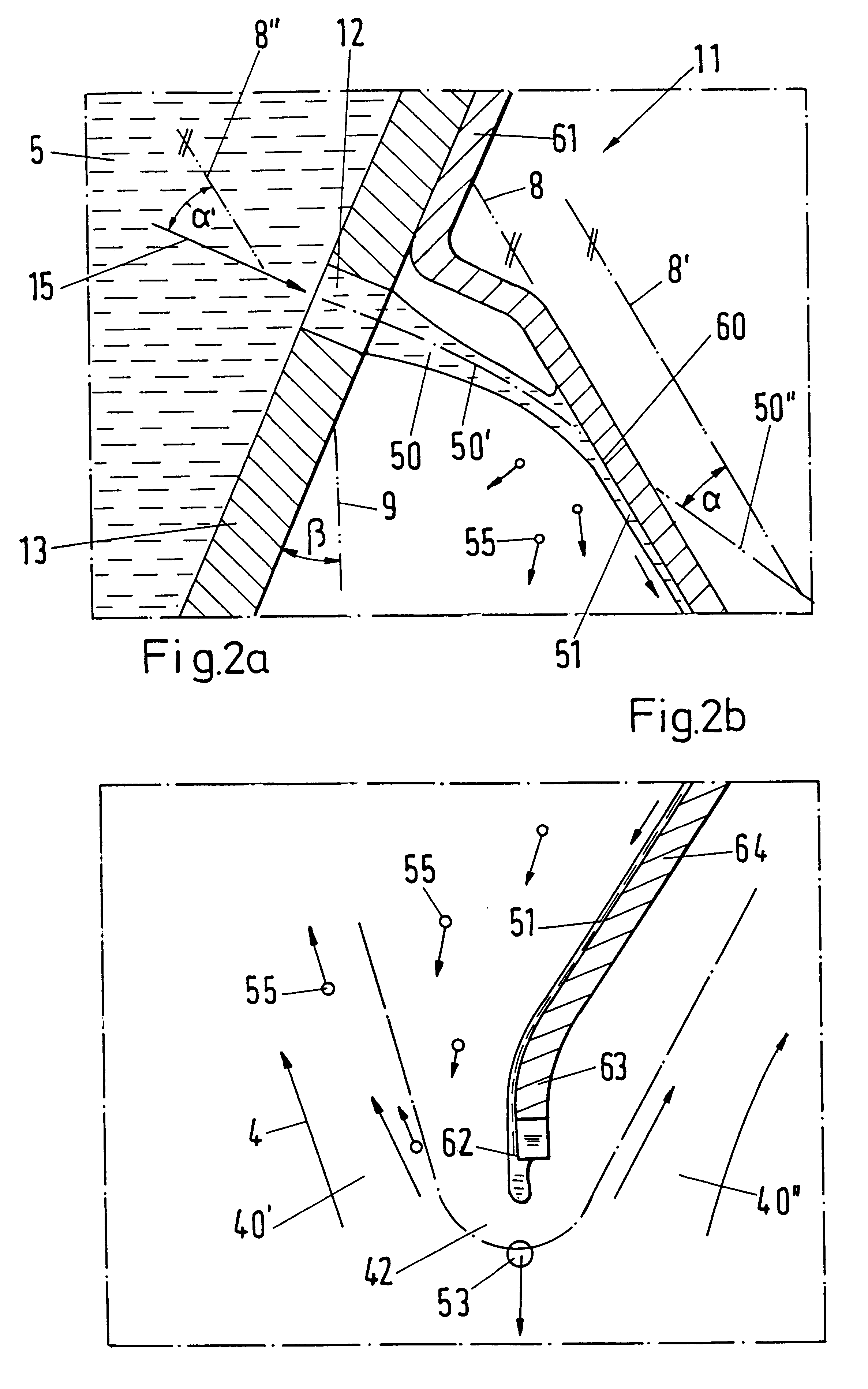
In FIG. 2a the surroundings of an outlet opening 12 of a distributor member 11 are shown as a sectional illustration for a distributor 1 in accordance with the invention. The outlet opening 12 is located in an inclined side wall 13. As a rule the side wall 13 is vertical; the angle .beta. measured from the vertical is thus equal to zero. The liquid 5 flows out in the direction 15 through the opening 12, subsequently forms a free jet 50, the centerline 50' of which is curved downwardly in accordance with gravitation, and is incident in the direction 50" onto a screen 6...


PUM

PropertyMeasurementUnit
anglesaaaaaaaaaa
anglesaaaaaaaaaa
incidence angleaaaaaaaaaa

Abstract

A liquid distributor for packing columns. The liquid distributor includes at least one tubular or trough-like distributor member including outlet openings for an output of liquid in the form of jets. Screens are arranged ahead of the outlet openings onto which the incident liquid jets are deformed to liquid films flowing off. The outlet openings screen the outlet openings against an upwardly flowing gas flow. In the event of a maximum output of liquid, the liquid jets are incident onto the screens at angles that are less than 60°, and even as much as less than 10°.

Description

1. Field of the InventionThe invention relates to a liquid distributor, in particular for packing columns, and to a column with a liquid distributor of this kind.2. Description of the Prior ArtA liquid distributor of this kind is known from EP 0 282 753 in which liquid emerges from outlet openings of tubular or trough-like distributor members and is incident as jets on screens which are formed as baffle plates (called conduction walls there). The liquid impacts at relatively high speed on the screen and distributes itself on the latter as a film of parabolic shape. This liquid distributor is provided for a packing column in which a gas is conducted in a counterflow to the liquid. A plurality of parallel distributor members subdivides the upwardly flowing gas into a plurality of partial flows. Drip edges of the screens are arranged beneath the distributor members inside stagnation zones of the gas flow.Material exchange processes in which very large volume or mass flows are possible ...

Claims


Application Information

Patent Timeline
Patent Type & Authority Patents(United States)
IPC IPC(8): B01D53/18B01D3/00B01D3/32B01J8/00
CPCB01D53/185B01D3/008
Inventor FISCHER, MARKUSMOSER, FELIX
Owner SULZER CHEMTECH AG
Why Eureka
Try Eureka