Ink tank coupling method, ink jet recording apparatus, and ink tank

a technology of ink jet and coupling portion, which is applied in the direction of printing, etc., can solve the problems of increased container size, ink leakage from the coupled portion, and damage to the coupled portion,

Inactive Publication Date: 2001-09-25
CANON KK
View PDF11 Cites 90 Cited by
  • Summary
  • Abstract
  • Description
  • Claims
  • Application Information

AI Technical Summary

Problems solved by technology

With a container having such a large size, however, the following specific problems due to an increase of the container size arise in point of connection to an ink tank unit.
This raises a risk that ink may leak from the coupled portion, or in the worst case, the coupled portion may be damaged; for example, the needle may be bent.
Particularly, in such a construction that the direction in which the needle is inserted is opposed to the direction in which the ink tank is inserted, if the ink tank is fixed offset from a predetermined position, an extra force is imposed on the coupled portion due to a condition where the needle and the ink supply port are not positively connected to each other, thus resulting in a risk that ink may leak from the coupled portion, or in the worst case, the coupled portion may be damaged; for example, the needle may be bent.

Method used


Image

  • Ink tank coupling method, ink jet recording apparatus, and ink tank
  • Ink tank coupling method, ink jet recording apparatus, and ink tank
  • Ink tank coupling method, ink jet recording apparatus, and ink tank

Examples


first embodiment

FIGS. 3 to 7 are explanatory views of an ink tank unit (main tank unit) receiving an ink tank (main tank) for a liquid ejection recording apparatus and the ink tank received in the ink tank unit according to the present invention.

The ink tank attached to the ink tank unit of the present invention will be first described with reference to three-dimensional perspective views shown in FIGS. 3A and 3B. FIG. 3A is a three-dimensional perspective view of the ink tank in a state where a connecting portion of the ink tank to needles of the ink tank unit, described later, is positioned at the top (i.e., in a posture during use), and FIG. 3B is a three-dimensional perspective view for explaining a bottom surface of the ink tank.

A main tank 1 comprises a rigid housing 11 and can contain a liquid, such as ink, directly inside the housing 11. The main tank 1 includes a first cap 2 in the form of a first projected portion having an atmosphere communicating port 12 through which the atmosphere is ...

second embodiment

This second embodiment differs from the above first embodiment in shapes of the upper guide and the click member.

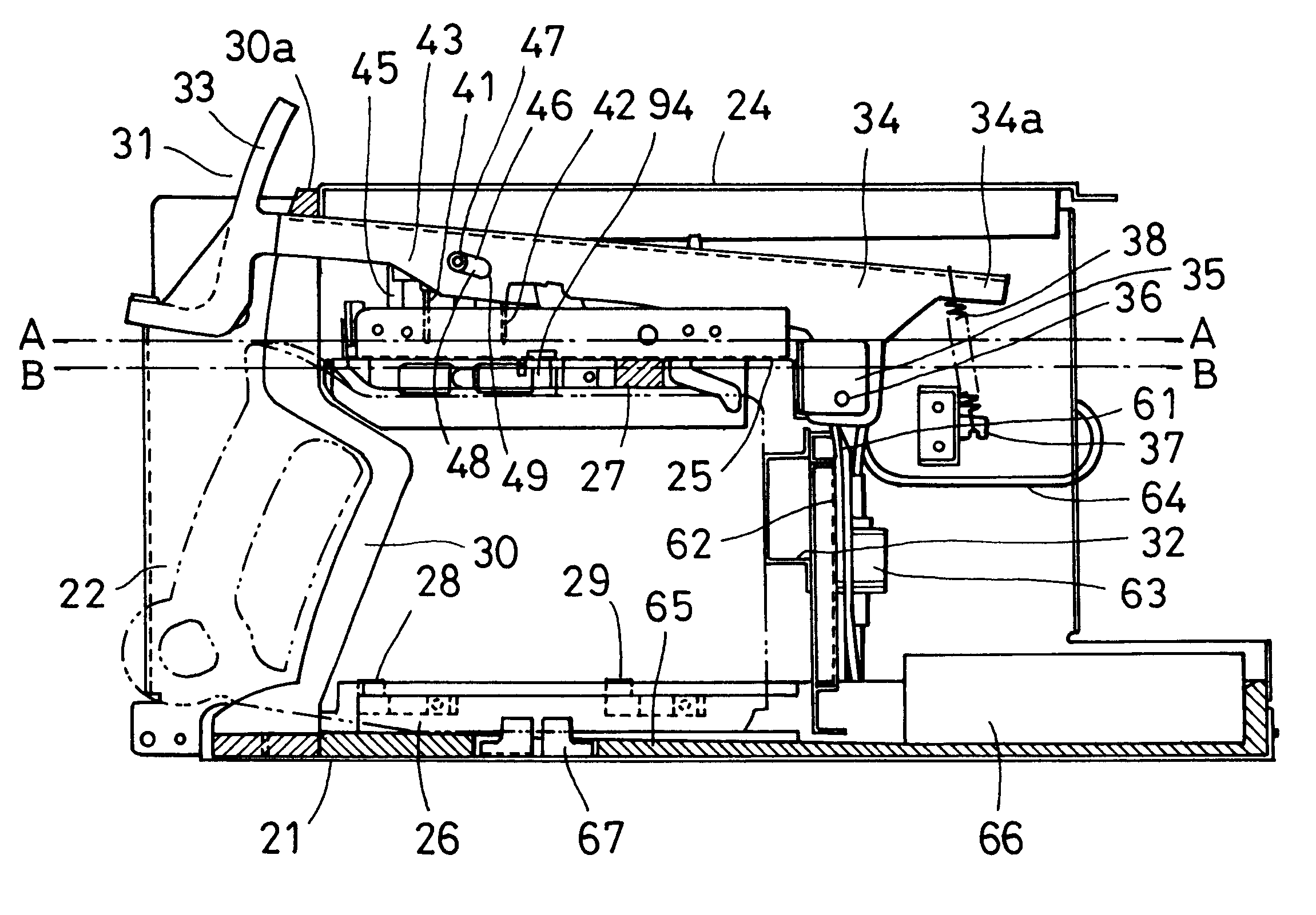
A click member 394 in this embodiment comprises a right click member 394R and a left click member 394L which are substantially symmetrical about the center line. The right click member 394R and the left click member 394L are both rotatable about a pivot shaft 395 fixedly provided on a central plate 25. A compression spring 396 always biases the right click member 394R clockwise and the left click member 394L counterclockwise. An upper guide 327 includes a U-shaped cap guide portion 328 comprising lateral abutment surfaces 328a, 328b and a perpendicular abutment surface 328c. The cap guide portion 328 serving as a U-shaped guide is opened in the direction of insertion of the tank. The cap guide portion 328 has a width enough to allow insertion of the caps of the main tank, but adapted to essentially prevent the caps from wobbling. Therefore, the main tank is positioned lat...

third embodiment

In the above first and second embodiments, the click member is constructed to press the first projected portion after the ink tank has been inserted, but it may be constructed to press the second projected portion.

FIGS. 18A and 18B are sectional views of a principal part of an ink tank unit according to a third embodiment of the present invention; FIG. 18A shows a state where an ink tank is being inserted into the ink tank unit, and FIG. 18B shows a state after the insertion. This third embodiment differs from the above first and second embodiments in that a click member 494 has a different shape and a cap 3 in the form of a second projected portion and having an ink supply port is pressed by a compression spring 496.

In this embodiment, therefore, when inserting the ink tank, users sense a click feel twice before release of the needle movement preventing means.

Further, in this embodiment, an upper portion of the ink tank is finally positioned by pressing the first cap 2 to abut a la...


PUM


Abstract

Disclosed is an ink tank coupling method for an ink jet recording apparatus including a recording head, an ink supply needle, and a moving unit for moving the ink supply needle to a predetermined position, the recording apparatus being able to detachably mount an ink tank containing ink supplied to the recording head. The method includes a step of holding and fixing the ink tank to a predetermined position by releasing a movement preventing unit which prevents movement of the ink supply needle caused by the moving unit, and pressing the ink tank to abut a reference surface with an operation of attaching the ink tank to the recording apparatus, and a step of inserting the ink supply needle to the predetermined position in the ink tank by the moving unit after the holding and fixing step. Disclosed also is an ink jet recording apparatus and an ink tank adapted for carrying out the ink tank coupling method with a relatively simple construction and with higher reliability of the coupling, while allowing users to recognize the proper coupling of the ink tank.

Description

1. Field of the InventionThe present invention relates to an ink tank coupling method for use with a liquid ejection recording apparatus in which a liquid such as ink is ejected to carry out recording, an ink jet recording apparatus, and an ink tank for use in the ink jet recording apparatus. More particularly, the present invention relates to an ink tank coupling method for use with a liquid ejection recording apparatus which is employed in an ink jet printing system consuming a large amount of ink, an ink jet recording apparatus, and a large-capacity ink tank mounted on the ink jet recording apparatus.2. Description of the Related ArtAn ink tank (liquid storing container) for use in an ink jet recording apparatus is constructed to be detachably attached to an ink tank unit, which serves as an ink tank receiving portion of the recording apparatus, in order that the ink tank can be easily replaced when ink is exhausted. The ink tank has an ink supply port which is closed by a rubber...

Claims


Application Information

Patent Timeline
Patent Type & Authority Patents(United States)
IPC IPC(8): B41J2/175
CPCB41J2/175B41J2/17509B41J2/17553B41J2/17523B41J2/1755B41J2/1752
Inventor SHIHOH, MAKOTOSATO, OSAMUIKKATAI, MASATOSHIMIYAZAKI, KYOTAARAKI, YOSHIMASA
Owner CANON KK
Why Eureka
Try Eureka