Method and apparatus for directional well logging with a shield having sloped slots

a shield and slot technology, applied in the field of well logging, can solve problems such as significant undesired em field components

Inactive Publication Date: 2001-10-02
SCHLUMBERGER TECH CORP
View PDF10 Cites 231 Cited by
  • Summary
  • Abstract
  • Description
  • Claims
  • Application Information

AI Technical Summary

Benefits of technology

A method and apparatus are provided for making directional measurements of the characteristics of earth formations surrounding a borehole. The disclosed methods and apparatus include the use of a new antenna shield designed to provide selec...

Problems solved by technology

However, under actual operating conditions, there are various factors t...

Method used


Image

  • Method and apparatus for directional well logging with a shield having sloped slots
  • Method and apparatus for directional well logging with a shield having sloped slots
  • Method and apparatus for directional well logging with a shield having sloped slots

Examples


Embodiment Construction

In the interest of clarity, not all features of actual implementation are described in this specification. It will be appreciated that although the development of any such actual implementation might be complex and time-consuming, it would nevertheless be a routine undertaking for those of ordinary skill in the art having the benefit of this disclosure.

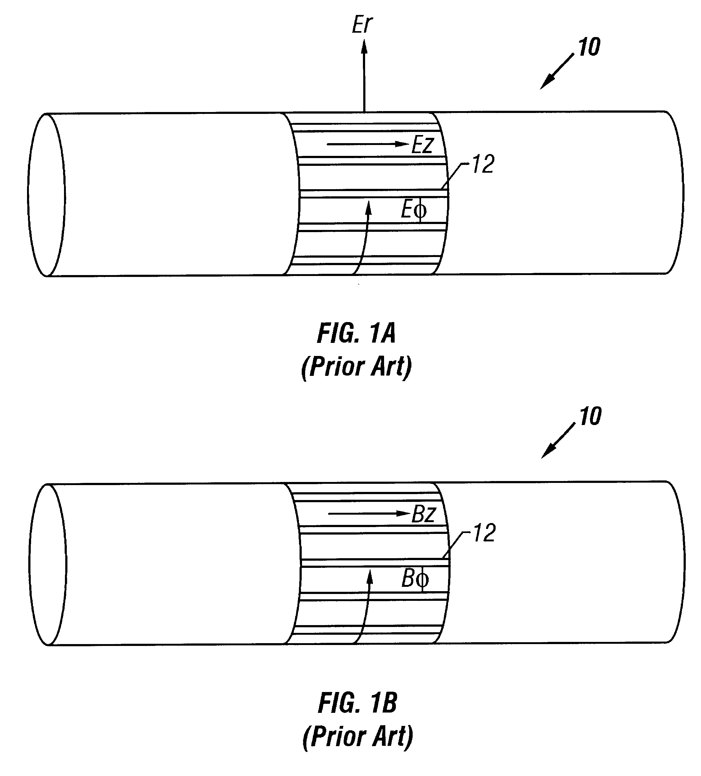
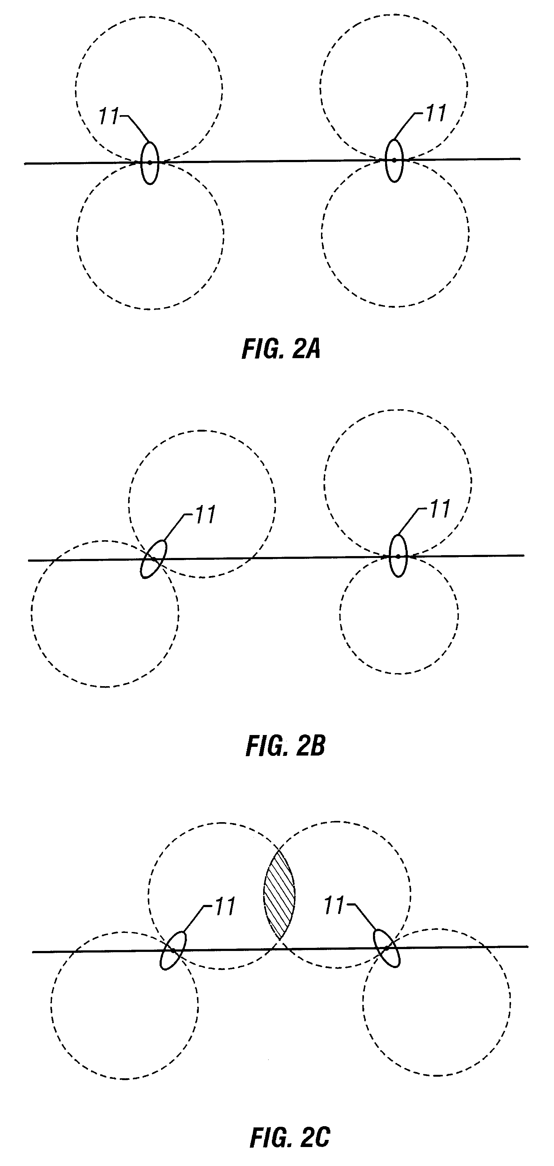
As described above, an energized transmitter coil on a logging tool will irradiate the surrounding formation with EM energy. The EM energy is sensed by one or more receiver coils on the tool. FIG. 2a shows the general field of coil 11 sensitivity to EM energy for a typical non-tilted (axial) coil 11 configuration. FIG. 2b shows the general field of coil 11 sensitivity for a coil 11 configuration where one coil 11 is tilted relative to the tool axis (represented by the solid line). FIG. 2c shows the general field of coil 11 sensitivity for a coil 11 configuration where both coils 11 are tilted relative to the tool axis. Maximum sensiti...


PUM


Abstract

Methods and apparatus for making directional measurements of earth formations surrounding a borehole. New antenna coil shield designs are utilized to provide selective attenuation of at least one electromagnetic energy field component as the component interacts with the shield. The new shields are implemented in several downhole tool configurations to provide azimuthally focused formation measurements. In effect, the new shield filters interacting electromagnetic energy field components to pass those components corresponding to a magnetic dipole oriented at an angle from the tool axis. The shields thereby alter a coil's envelope of influence to electromagnetic energy. The new shields also form part of a system for making directional measurements while drilling.

Description

1. BACKGROUND OF THE INVENTION1.1 Field of the InventionThis invention relates to the field of well logging and, more particularly, to an improved method and apparatus for making focused downhole measurements of formation characteristics. The invention has general application in the well logging art, but is particularly useful in logging-while-drilling.1.2 Description of Related ArtResistivity logging is a well-known form of electromagnetic ("EM") propagation logging. Resistivity logging is used for measuring and evaluating the characteristics of potential hydrocarbon bearing zones in subsurface formations. Porous formations having high resistivity generally indicate the presence of hydrocarbons, while low resistivity formations are generally water saturated.In conventional logging techniques, a number of antennae or coils are mounted on a well tool. The tool is lowered into a borehole on the end of a cable, or wireline. An alternating current energizes one or more transmitter coils...

Claims


Application Information

Patent Timeline
IPC IPC(8): G01V3/30G01V3/18
CPCG01V3/30
Inventor CLARK, BRIANROSTHAL, RICHARD A.HOMAN, DEAN M.OMERAGIC, DZEVATBONNER, STEPHEN D.CHESSER, SCOTT S.BARBER, THOMAS D.
Owner SCHLUMBERGER TECH CORP
Why Eureka
Try Eureka