Pool cleaner with open-ended pin supported flapper valve

a technology of open-ended pins and flapper valves, which is applied in the direction of gyms, buildings, construction, etc., can solve the problems of system shutdown, requiring frequent cleaning, and limiting the size of the debris that can be collected by the cleaner

Inactive Publication Date: 2001-10-09
HAYWARD IND INC
View PDF10 Cites 39 Cited by
  • Summary
  • Abstract
  • Description
  • Claims
  • Application Information

AI Technical Summary

Problems solved by technology

However, the offset restricting orifice, while necessary to initiate the flapper valve reciprocation, significantly limits the size of the debris that can be collected by the cleaner.
In addition, debris often becomes trapped in the restricting orifice, causing system shutdown and requiring frequent cleanouts.
Furthermore, the hydraulic restriction created by the orifice causes an increased electrical load on the pool pump, thereby shortening the life of the system.

Method used


Image

  • Pool cleaner with open-ended pin supported flapper valve
  • Pool cleaner with open-ended pin supported flapper valve
  • Pool cleaner with open-ended pin supported flapper valve

Examples


Embodiment Construction

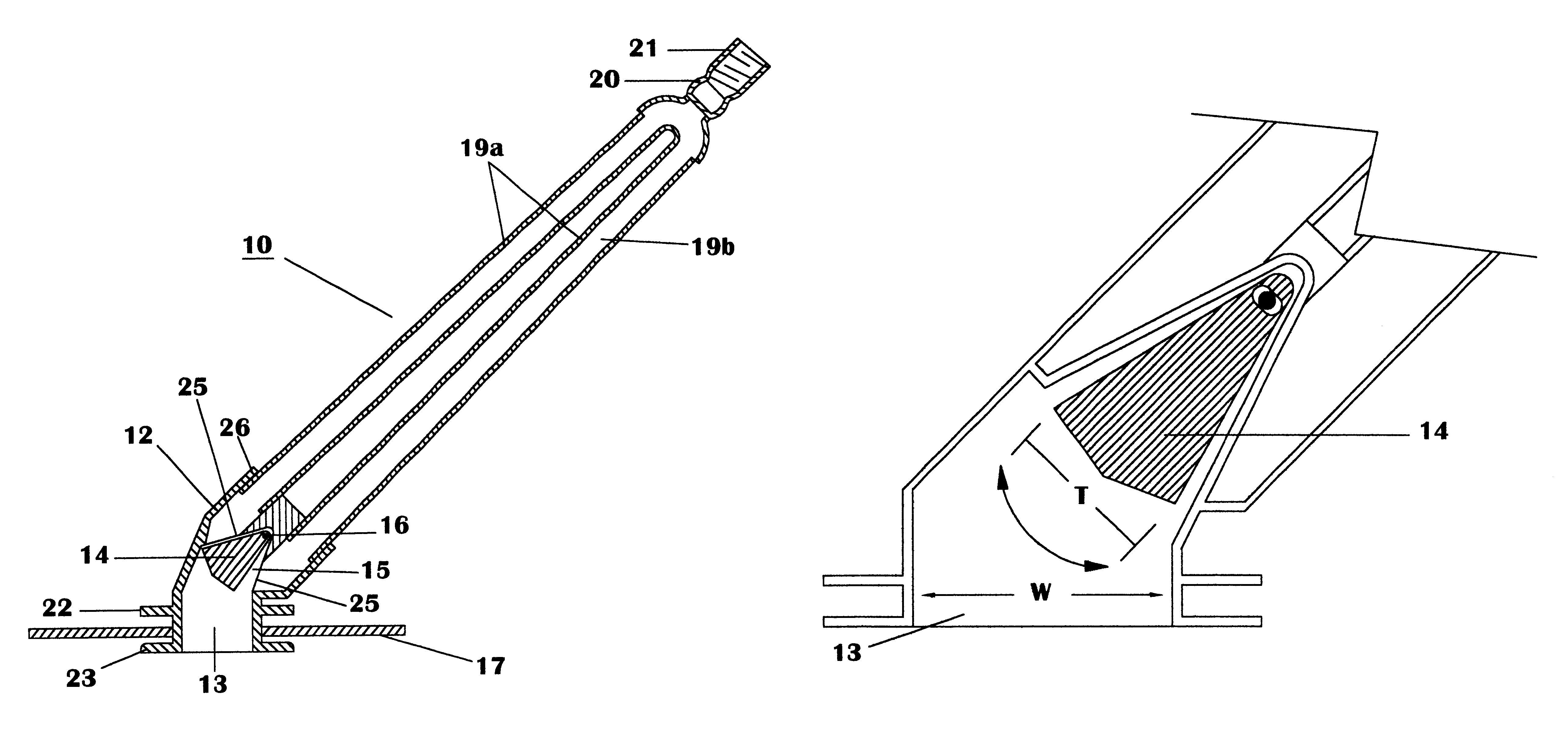
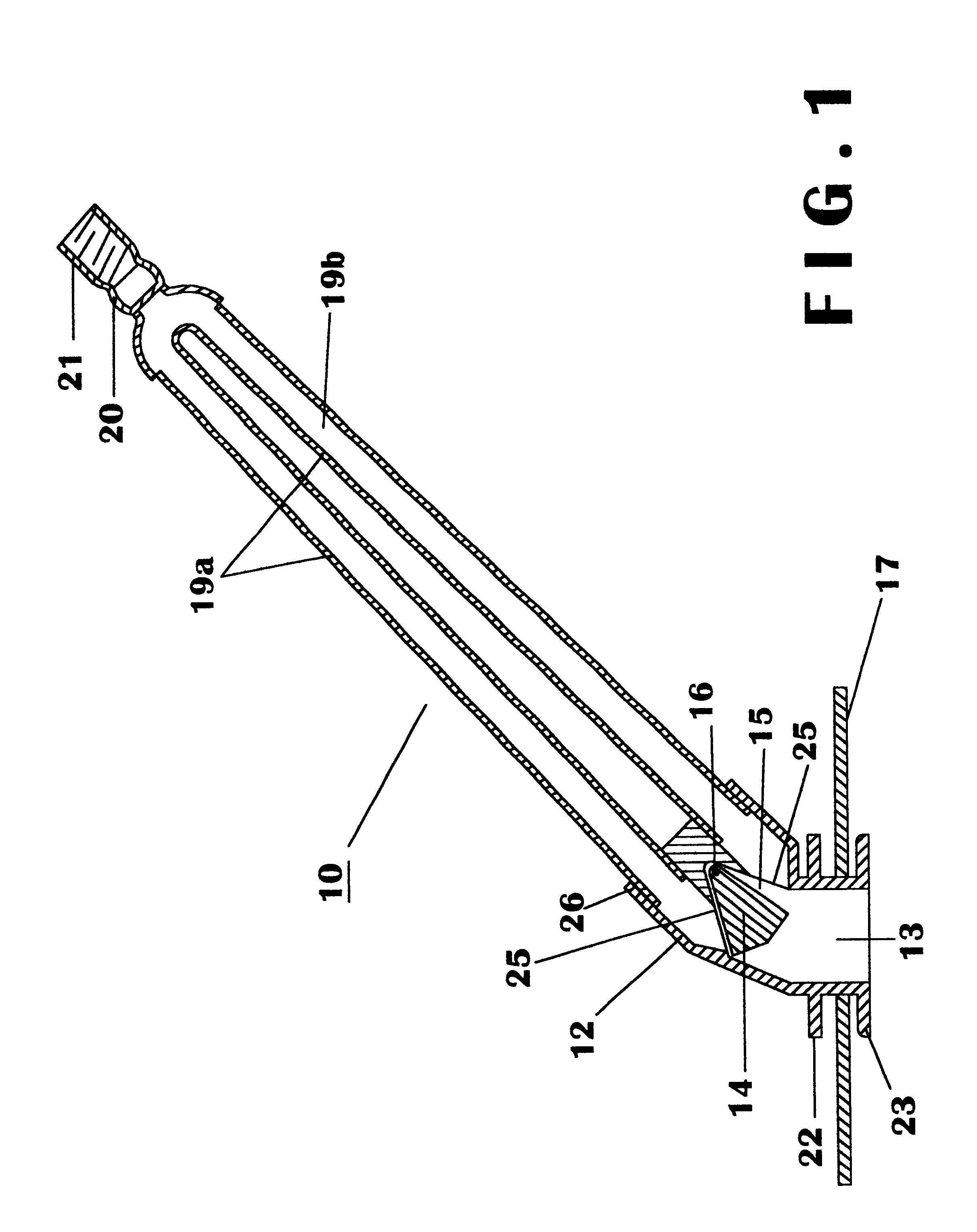
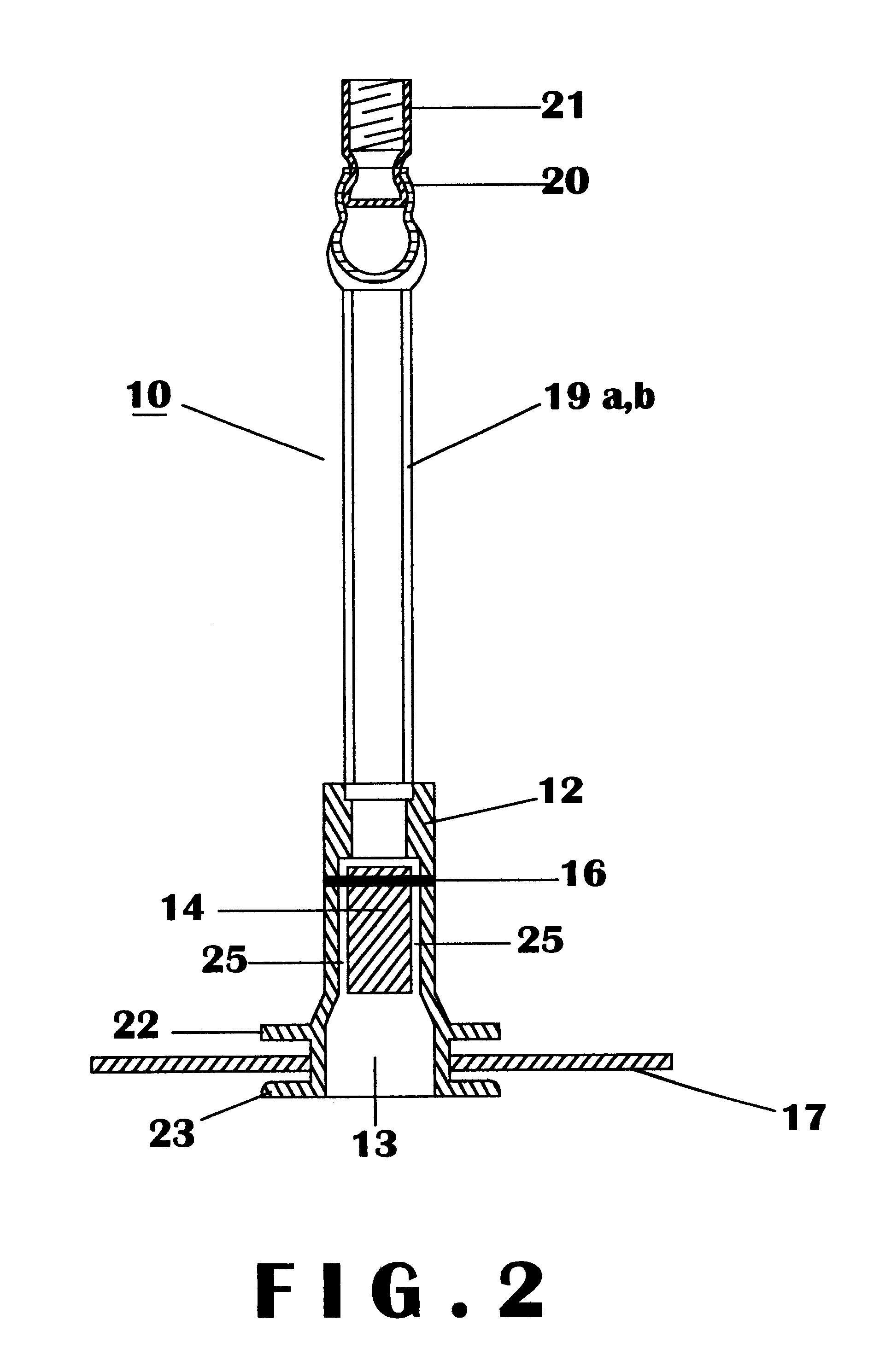
The invention is designed as an automatic swimming pool cleaner device. With reference to FIGS. 1 and 2, the automatic swimming pool cleaner apparatus 10 consists of a hollow head 12 which has within it a suction chamber 13 and above which is a generally triangular shaped flapper valve 14 with faces 15, pivoted about a shaft 16. About head 12 is a flexible disc 17 which is normally round in shape and held in place by upper flange 22 and lower flange 23. Above the flapper valve 14 in both the direction of water flow and normal operating orientation are two impact tubes 19a, 19b that are usually round in diameter and of a length depending upon the desired embodiment.

The water is directed into one impact tube 19a and then to the other impact tube 19b repetitively. The interruption of the flow generates an impact by the change in the water's kinetic energy which in turn reacts on the mass of the pool cleaner 10 and causes a vibratory motion that drives the pool cleaner 10 about the pool...


PUM


Abstract

A domestic automatic swimming pool cleaner which randomly travels about and cleans the walls and bottom surfaces of a swimming pool includes two parallel or non-parallel impact tubes, the top ends of which are connected to a flexible suction hose which in turn is connected to the suction side of the pool's filter pump. The bottom ends of the tubes are served intermittent shots of water by a hinged self-starting flapper valve with an unrestricted upstream opening in the cleaner's pool surface contacting head. By the action of the valve alternately delivering pool water to the two tubes, kinetic forces are generated which move the automatic pool cleaner about the pool.

Description

1. Field of the InventionThis invention relates generally to a device for the automatic cleaning of swimming pools, and more specifically to an improved and efficient suction-type automatic swimming pool cleaner.2. Description of the Prior ArtPrior art has shown that a swimming pool may be cleaned automatically by a device using a cleaning head which engages the pool surfaces to be cleaned and is connected to one or a pair of tubes (either parallel or non-parallel) with a valve mechanism that interrupts the flow of pool water through the cleaning device by either periodically interrupting the constant flow of water through the single tube, or alternately delivering water through either of the pair of tubes. These suction type automatic swimming pool cleaners are typically powered by the flow of water flowing from the pool through the cleaning head, past a flapper valve, through the tube (or tubes), through a flexible hose normally associated with suction cleaners, and finally drawn ...

Claims


Application Information

Patent Timeline
Patent Type & Authority Patents(United States)
IPC IPC(8): E04H4/00E04H4/16
CPCE04H4/1663
Inventor RIEF, DIETER J.RIEF, MANUELA
Owner HAYWARD IND INC
Why Eureka
Try Eureka