Intraocular lens insertion device

a technology of intraocular lens and insertion device, which is applied in the field of intraocular lens insertion device, can solve the problems of obsolete anterior chamber lens, inability to use intraocular lens, and inability to meet patient needs

Inactive Publication Date: 2001-10-09
SUGIURA TAKESHI
View PDF7 Cites 53 Cited by
  • Summary
  • Abstract
  • Description
  • Claims
  • Application Information

AI Technical Summary

Problems solved by technology

In cataract surgery at this period, the intraocular lens could not be used, and the patient required very thick eyeglasses for correcting an intense hypermetropia.
However, the anterior chamber lens caused complications such as bullous keratopa

Method used


Image

  • Intraocular lens insertion device
  • Intraocular lens insertion device
  • Intraocular lens insertion device

Examples


Embodiment Construction

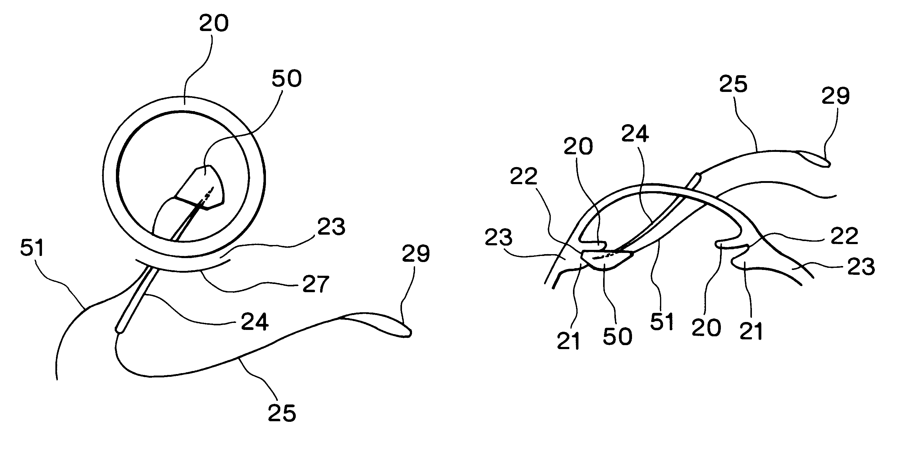
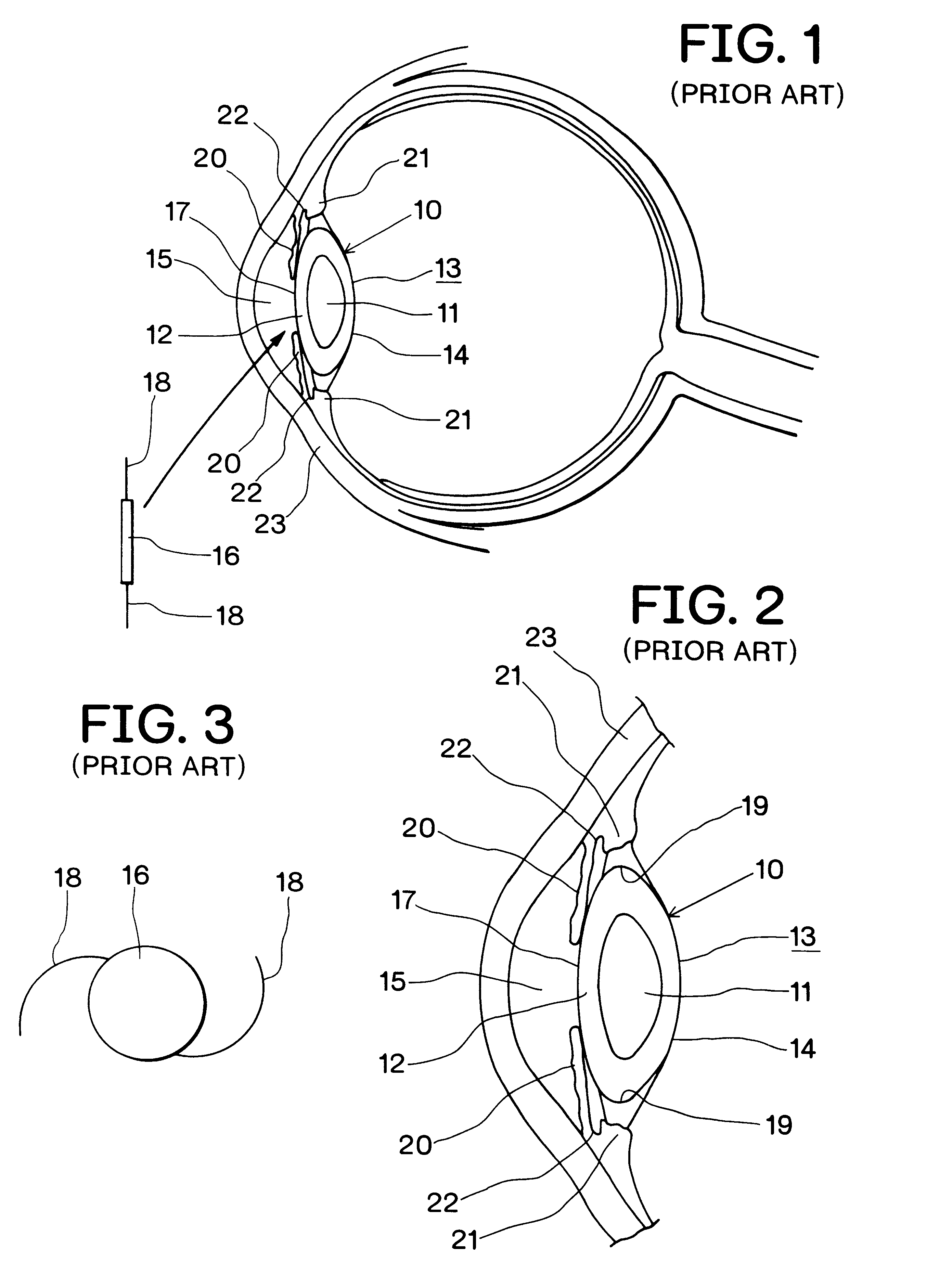
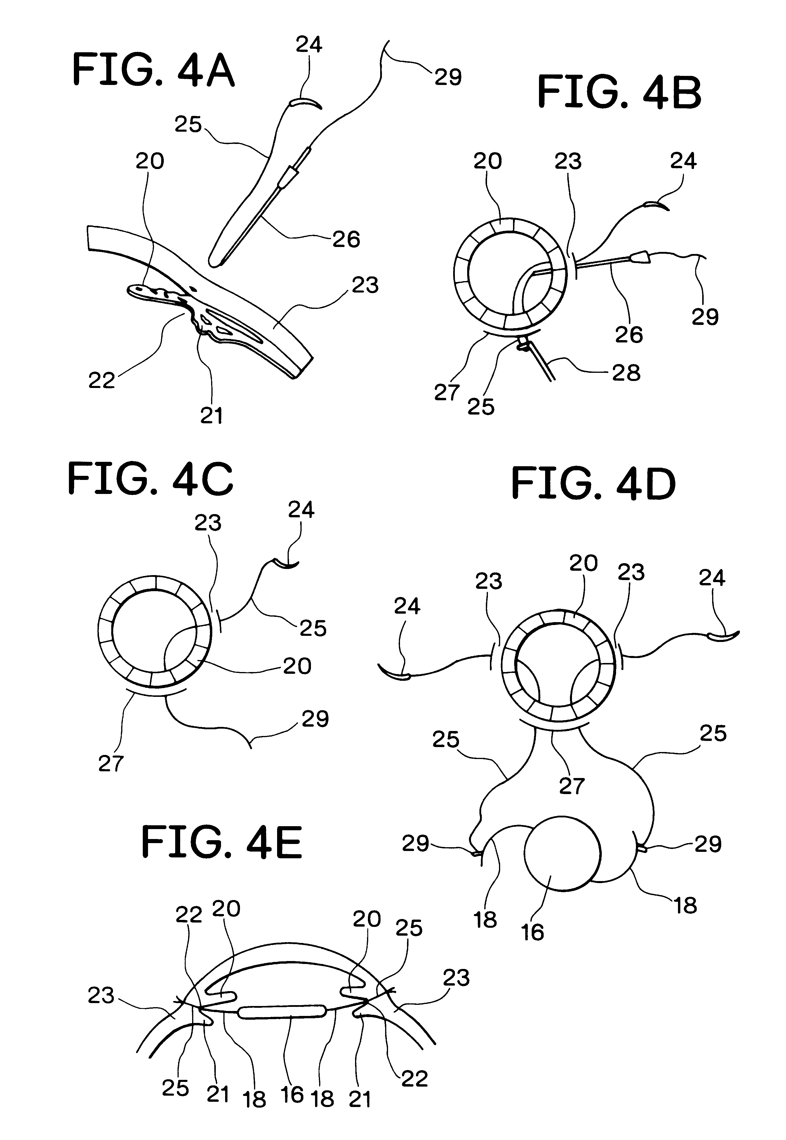
The preferred embodiment of the present invention will be described with reference to the accompanying drawings. As shown in FIG. 6 to FIG. 8, an intraocular lens insertion device according to the present invention comprises a pad 50 formed by an elastic element harmless to a living body such as silicon rubber or silicon sponge, and a drawing thread 51 mounted at a rear portion of the pad 50. The insertion device is used when the posterior chamber lens 16 is mounted on an eye which has no lens capsule 13, i.e., no site for supporting the posterior lens 16.

The pad 50 is substantially arc-shaped in a plan view, and an upper face 52 of the pad 50 is substantially flat as shown in FIG. 7. An inclined surface 53' on the front side of a lower surface 53 of the pad 50 is inclined toward the upper surface 52, where a taper-shaped insert portion 54 is formed. The pad 50 has a thickness of 1.0 to 2.0 mm at the thickest center thereof. While in use, as shown in FIG. 9A, a tip end of the straig...


PUM


Abstract

An intraocular lens insertion device comprises a pad formed by an elastic element harmless to a living body, a drawing thread mounted on a rear portion of the pad, and an insert portion formed at a front portion of the pad. The insert portion has a shape suitable to fit into a ciliary sulcus of an aphakic eye. The pad has a thickness capable of covering a tip end of a surgical needle.

Description

The present invention relates to an intraocular lens insertion device, and, more particularly, to an insertion device which is employed when a posterior chamber lens is sutured on an aphakic eye from which a posterior capsule of lens has been extracted or lost due to cataract surgery, accident or injury.PRIOR ARTConventionally, a lens whitened by a cataract is extracted by surgical means. As shown in FIG. 1 and FIG. 2, a lens 10 has a nucleus 11 and a cortex 12, and the entire is capsulated by a lens capsule 13. At a time when an intraocular lens was not developed, the nebular or whitened lens 10 was extracted by ICCE (Intracapsular Cataract Extraction) together with the entire lens capsule 13 or was extracted by ECCE (Entracapsular Cataract Extraction) while a posterior capsule 14 of the lens capsule 13 was left. In cataract surgery at this period, the intraocular lens could not be used, and the patient required very thick eyeglasses for correcting an intense hypermetropia.Thereaft...

Claims


Application Information

Patent Timeline
IPC IPC(8): A61F2/16A61B19/00A61F9/007A61F2/14A61L27/00
CPCA61F2/1662A61B2019/481A61B2090/08021
Inventor SUGIURA
Owner SUGIURA TAKESHI
Why Eureka
Try Eureka