Optical signal transmission network with fiber-break detection

a technology of optical signal transmission network and fiber break detection, which is applied in the direction of optical apparatus testing, transmission monitoring, instruments, etc., can solve the problems of unidirectional amplifier/repeater in such a system, use of conventional otdr launching a probe, and inconvenient operation

Inactive Publication Date: 2001-10-09
ALCATEL LUCENT SAS
View PDF23 Cites 42 Cited by
  • Summary
  • Abstract
  • Description
  • Claims
  • Application Information

AI Technical Summary

Benefits of technology

The network may comprise an additional optical coupling means communicating between said other fibre, to the output side of the amplifier / repeater, and said one of the fibres and including a second filter which is arranged to permit transfer of a test signal wavelength between the inbound and outbound fibre but which prevents transfer of a unwanted traffic signal.

Problems solved by technology

The amplifier / repeater in such a system are unidirectional and this prevents the use of conventional OTDR launching a probe pulse and detecting the backscattered signal on the same fibre.
This is an imprecise indication and does not permit the exact location of the break to be determined by time domain reflectometry.
The coupling factor has to be sufficiently small to prevent significant degradation of the traffic signals and this results in low sensitivity of detection of OTDR due to low levels of test signal transferred.

Method used


Image

  • Optical signal transmission network with fiber-break detection
  • Optical signal transmission network with fiber-break detection
  • Optical signal transmission network with fiber-break detection

Examples


Embodiment Construction

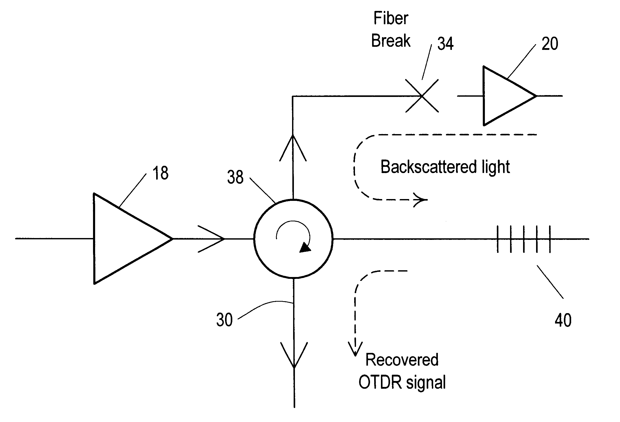
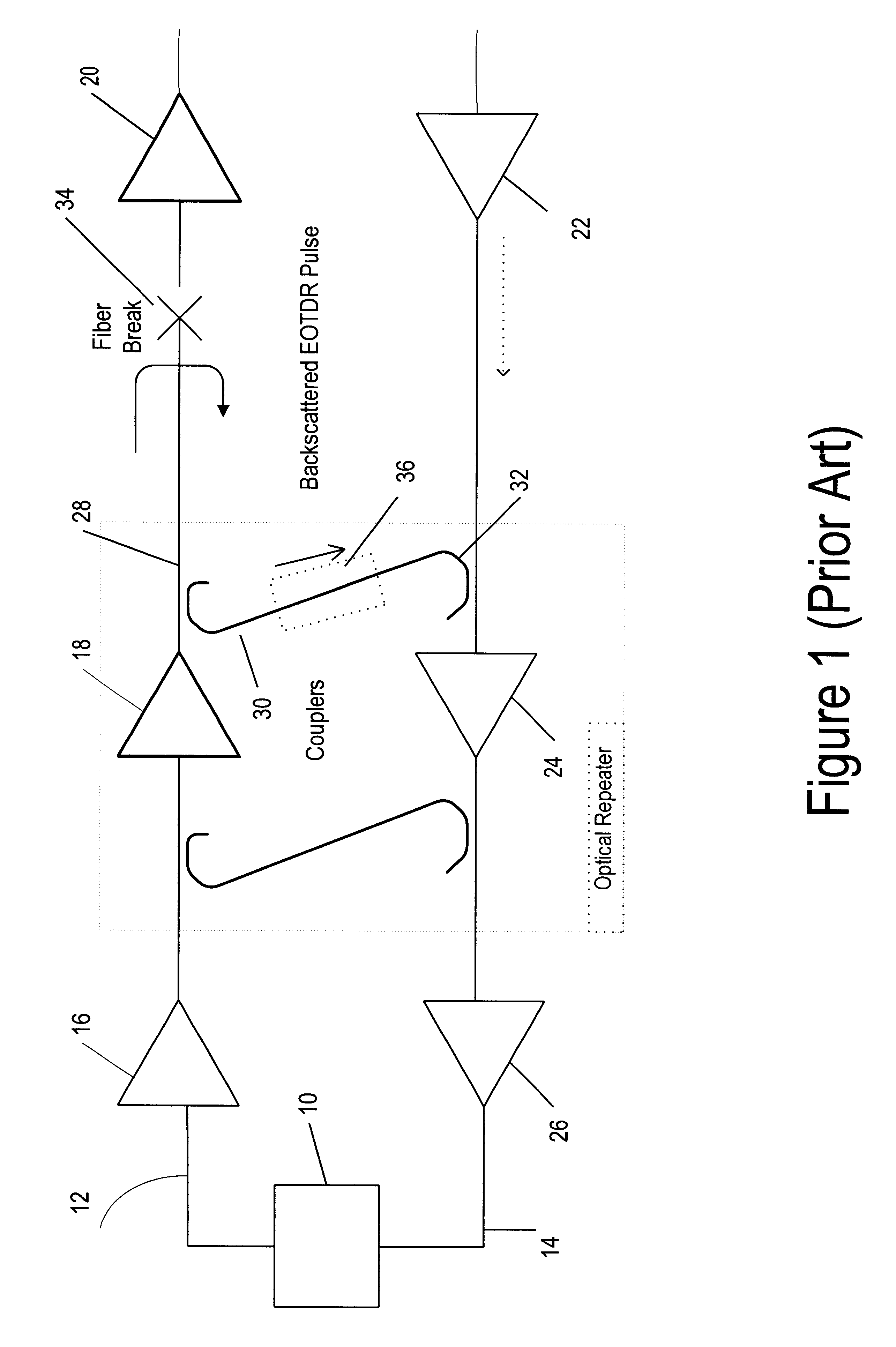
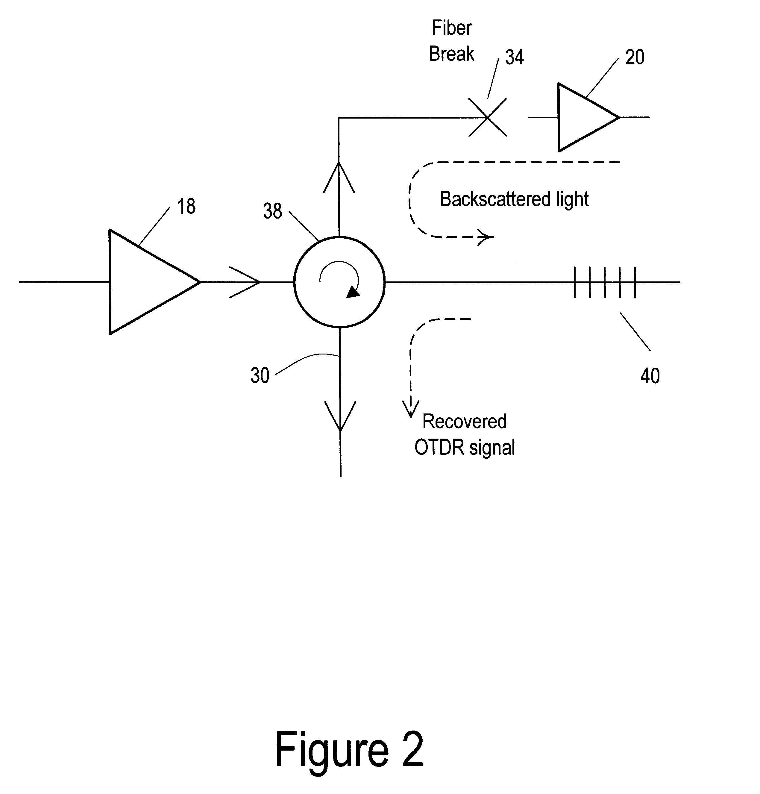
Referring now to FIG. 1 there is shown a prior art bidirectional long haul optical transmission system such as is described in reference 1 previously referred to. In this system a transmitter / receiver terminal 10 is coupled to an outbound fibre 12 for transmission signals and an inbound fibre 14 for receiving signals. The terminal 10 has the capability of providing a specific wavelength signal for OTDR purposes on the outbound fibre. The outbound and inbound fibres are routed via optical amplifiers / repeaters 16, 18, 20, 22, 24, 26 three of which are shown in each line. An optical directional coupler 28 is provided following amplifier / repeater 18 of the outbound line and is arranged to tap a proportion of the optical signal from the line, The coupler is coupled via a fibre 30 to the inbound line at the input to amplifier / repeater 24 via a second directional coupler 32. A break in the outbound line is shown at 34. In use, to detect the break, a test signal is sent from terminal 10 and...


PUM


Abstract

A bi-directional optical signal transmission network comprises an outbound (12) and an inbound (14) fibre each including an optical amplifier / repeater (18 / 24). An optical coupling (30, 38, 40) communicates between one of the fibres (12) to the output side of the amplifier / repeater (18) and the other fibre (14). The coupling includes a filter (40) which is arranged to permit transfer of a test signal wavelength between the outbound (12) and the inbound (14) fibre but which prevents transfer of unwanted traffic signal.

Description

BACKGROUND OF INVENTIONThis invention relates to fibre break detection in optical signal transmission networks and more particularly to such networks employing optical amplifiers.Optical fibre break detection is well known in which a signal is sent from one end of the fibre, is reflected from the break back to the sending end and used to determine the break position as a function of the time delay between sending and receiving back the signal. Such a system is known as Optical Time Domain Reflectometry (OTDR). In the case of long haul optical transmission networks it is necessary to employ one or more amplifier / repeater in order to compensate for signal degradation which occurs with increasing distance along the fibre. The amplifier / repeater in such a system are unidirectional and this prevents the use of conventional OTDR launching a probe pulse and detecting the backscattered signal on the same fibre.Long haul amplified / repeated optical transmission systems normally employ pairs o...

Claims


Application Information

Patent Timeline
Patent Type & Authority Patents(United States)
IPC IPC(8): H04B10/08H04B10/071H04B10/25G01M11/00
CPCH04B10/071H04B10/2503H04B10/2589
Inventor SPENCER, GEOFFREY
Owner ALCATEL LUCENT SAS
Why Eureka
Try Eureka