Motion analysis system

a motion analysis and motion technology, applied in the field of gait kinematics measurement methods and apparatuses, can solve the problems of limited cumbersome ways to measure distance and speed, limited walking/running routes, and failure to gain wide spread us

Inactive Publication Date: 2001-10-16
GARMIN
View PDF22 Cites 457 Cited by
  • Summary
  • Abstract
  • Description
  • Claims
  • Application Information

AI Technical Summary

Benefits of technology

The purpose of the device described herein is to provide a means to measure and display several gait parameters (that may include instantaneous and average accelerations and velocities as well...

Problems solved by technology

From an athletic point of view, runners, joggers and walkers often like to know how far they have journeyed and how fast they have traveled, but have had only limited cumbersome ways to measure distance and speed.
This method suffers from several limitations including (i) limited walking/running routes, (ii) speed indication at measured intervals only and (iii) only an average velocity is determined over the given distance.
However, they have failed to gain wide spread use, because these devices are essentially limited to stride counting.
This approach is inaccurate because an individual's stride length changes considerably from day to day or even within one session due to changes in terrain, fatigue, interval training, or other factors.
The majority of the patented pedometers are simply different methods of stride counting and do n...

Method used


Image

  • Motion analysis system
  • Motion analysis system
  • Motion analysis system

Examples


second embodiment

the invention is shown and will be described with reference to FIGS. 1A to 16A inclusive. Like reference numerals are used to indicate like parts in all embodiments.

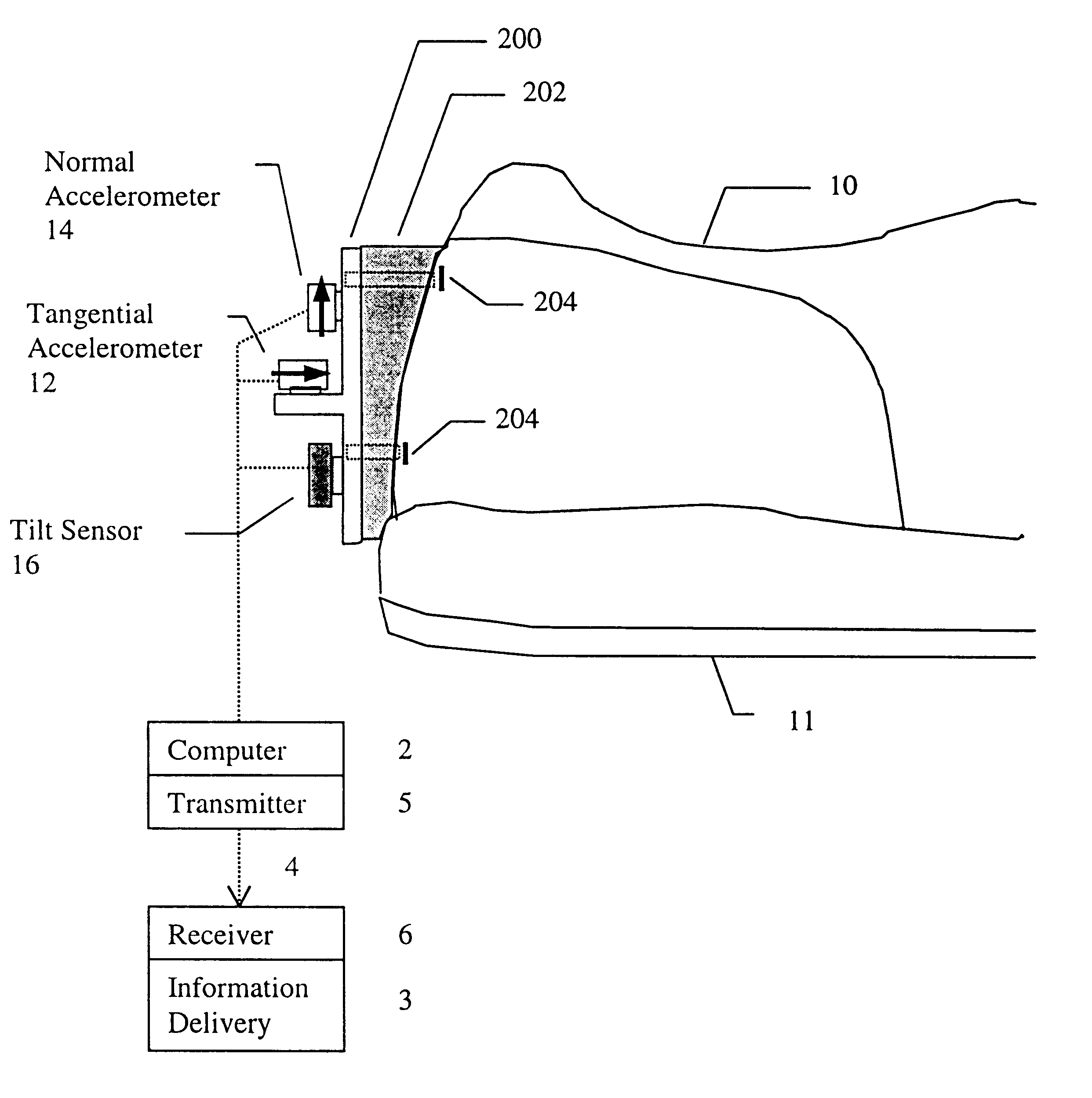
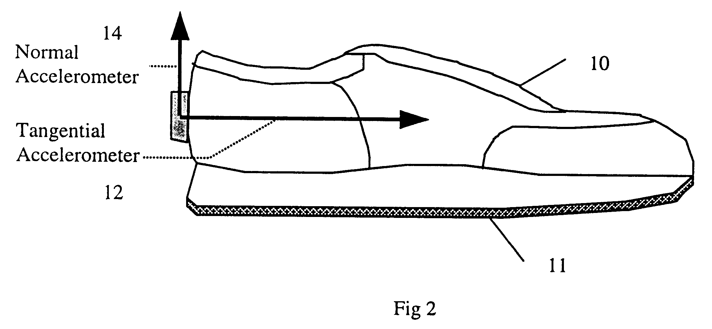
Accelerometers are placed on the foot in essentially the same manner as described above so that the normal accelerations, a.sub.n, tangential accelerations, a.sub.t, and angular accelerations, .alpha., preferably about the intersection 104 of the tangential and normal acceleration vectors a.sub.t and a.sub.n respectively can be simultaneously measured (see FIG. 1A). The normal accelerometer measures 14 acceleration perpendicular to the base or sole 11 of the foot or shoe 10 which as above described provides the datum plane 100 defining surface 11 that defines the datum plane 100 for each stride when the sole 11 is at rest in the stance phase A of each stride. The tangential accelerometer 12 is sensitive to accelerations parallel to the base or sole 11 of the foot or shoe 10. The absolute direction of these accelerations ...


PUM


Abstract

A device comprised of at least a pair of accelerometers and a tilt sensor mounted in fixed relation to a datum plane defining surface (sole of a shoe) may be used for extracting kinematic variables including linear and rotational acceleration, velocity and position. These variables may be resolved into a selected direction thereby permitting both relative and absolute kinematic quantities to be determined. The acceleration is determined using a small cluster of two mutually perpendicular accelerometers mounted on a shoe. Angular orientation of the foot may be determined by double integration of the foot's angular acceleration (which requires a third accelerometer substantially parallel to one of the two orthogonal accelerometers). The two orthogonal accelerations are then resolved into a net horizontal acceleration or other selected direction which may be integrated to find the foot velocity in the selected direction. The average of the foot velocity corresponds to the subject's gait speed.

Description

FIELD OF THE INVENTIONThe invention relates to a method and apparatus for measuring gait kinematics such as, for example, acceleration, velocity and position of gait based on foot movement analysis.Background of the InventionThe measurement and characterization of gait (i.e. human or animal) is performed by a wide range of methods. At one end of the scale is the measurement and analysis possibilities found in a well equipped bio-mechanical lab. The equipment in these labs typically includes automated 3D optical measurement systems, force plates and physiological output indicators. The output from these transducers are fed into a central computer that enables a wide range of analysis and display possibilities. At the other end of the spectrum is the simplified analysis performed with a ruler, stopwatch and trained clinical observations.The reasons determining gait kinematic properties (such as acceleration, velocity and position) range from: (i) personal interest, (ii) training and p...

Claims


Application Information

Patent Timeline
IPC IPC(8): A61B5/103A63B69/00G01P1/12G01C22/00G01P1/00G01P15/18A61F2/50A61F2/76A63B24/00
CPCA63B69/0028G01C22/006G01P1/127G01P15/18A61B5/112A61F2002/7615A61F2002/764A63B2220/40A61B2562/0219
Inventor FYFE, KENNETH R.ROONEY, JAMES K.FYFE, KIPLING W.
Owner GARMIN
Why Eureka
Try Eureka