Angular position sensor with inductive attenuating coupler

a technology of inductive attenuation and angular position sensor, which is applied in the direction of electrical/magnetically converting sensor output, instruments, process and machine control, etc., can solve the problems of inability to use detected amplitude, inability to achieve linearly proportionate attenuation, and inability to achieve the effect of improving angular position sensor

Inactive Publication Date: 2001-10-16
BEI SENSORS & SYST
View PDF5 Cites 103 Cited by
  • Summary
  • Abstract
  • Description
  • Claims
  • Application Information

AI Technical Summary

Benefits of technology

It is therefore a general object of the present invention to provide an improved angular position sensor. In accordance with the above object there is provided an angular position sensor for sensing rotation about an axis comprising a pair of spaced substantially circular transmit and receive disks juxtaposed on the axis facing each other with a coupler disk between them, the coupler disk being rotatable about the axis. The receive disk carries a predetermined number of independent inductive coils segmentally arranged in a circular pattern around the receive disk. The transmitter disk carries coil means driven by a signal service at a predetermined radio frequency for inductive coupling to the coils of the receive disk. The coupler disk carries a symmetrical conductive pattern for attenuating the inductive coupling, the pattern having rotary angular positions of maximum and minimum attenuation with respect to any one of the plurality of inductive coils carried by the receive disk, intermediate positions of the pattern between maximum and minimum providing a substantially linearly proportionate attenuation. Means are connected to the plurality of coils carried by the receive disk for demodulating and summing induced transmitted signals from the signal source for each angular position of the coupler, the summation producing a substantially sinusoidal waveform whose phase shift varies in proportion to the coupler rotation. Means are provided for the sensing the phase shift.

Problems solved by technology

However, the use of a detected amplitude, especially for automotive and industrial applications is not suitable.
Errors resulting from the foregoing uncertainty will not provide acceptable performance.

Method used


Image

  • Angular position sensor with inductive attenuating coupler
  • Angular position sensor with inductive attenuating coupler
  • Angular position sensor with inductive attenuating coupler

Examples


Embodiment Construction

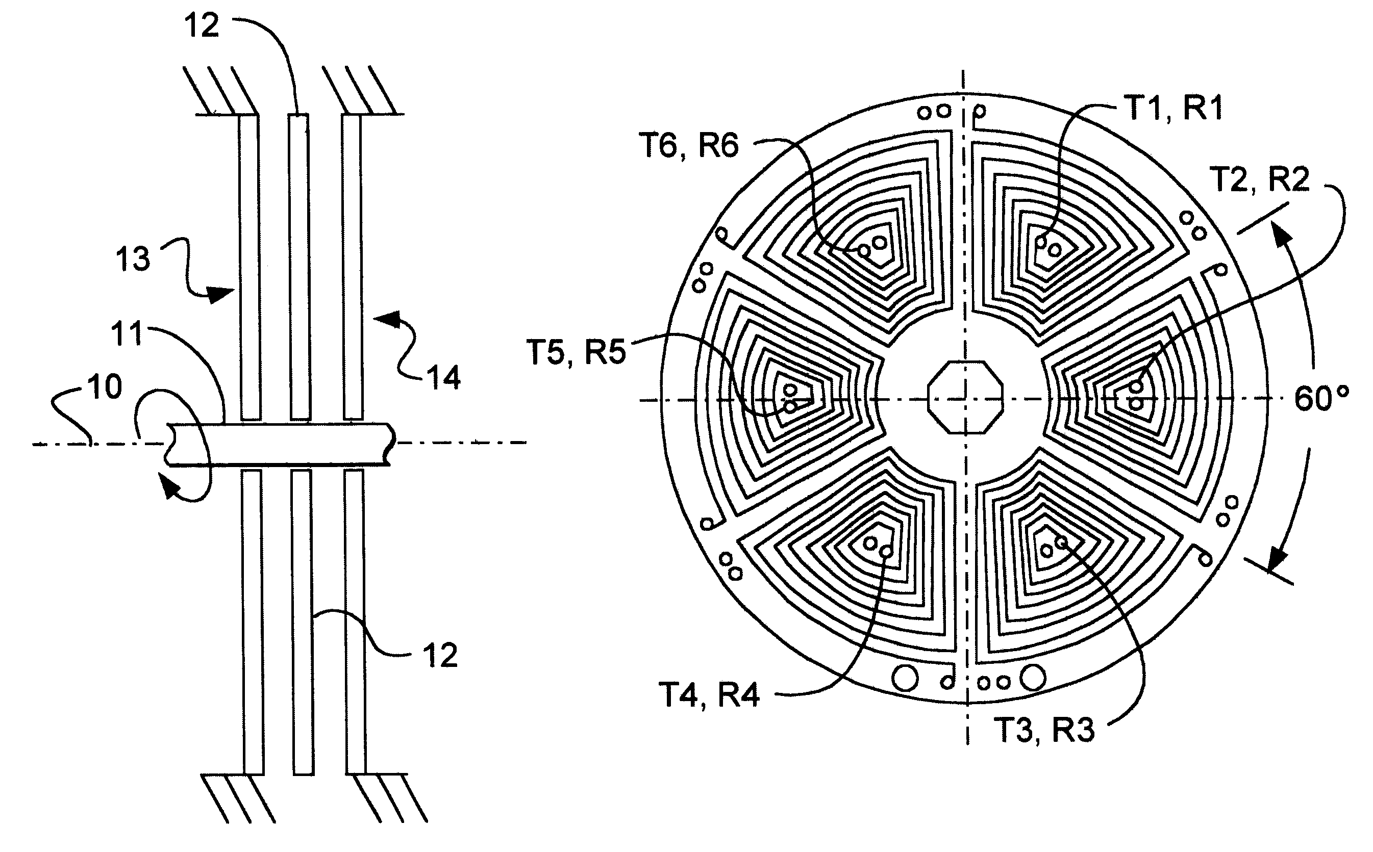
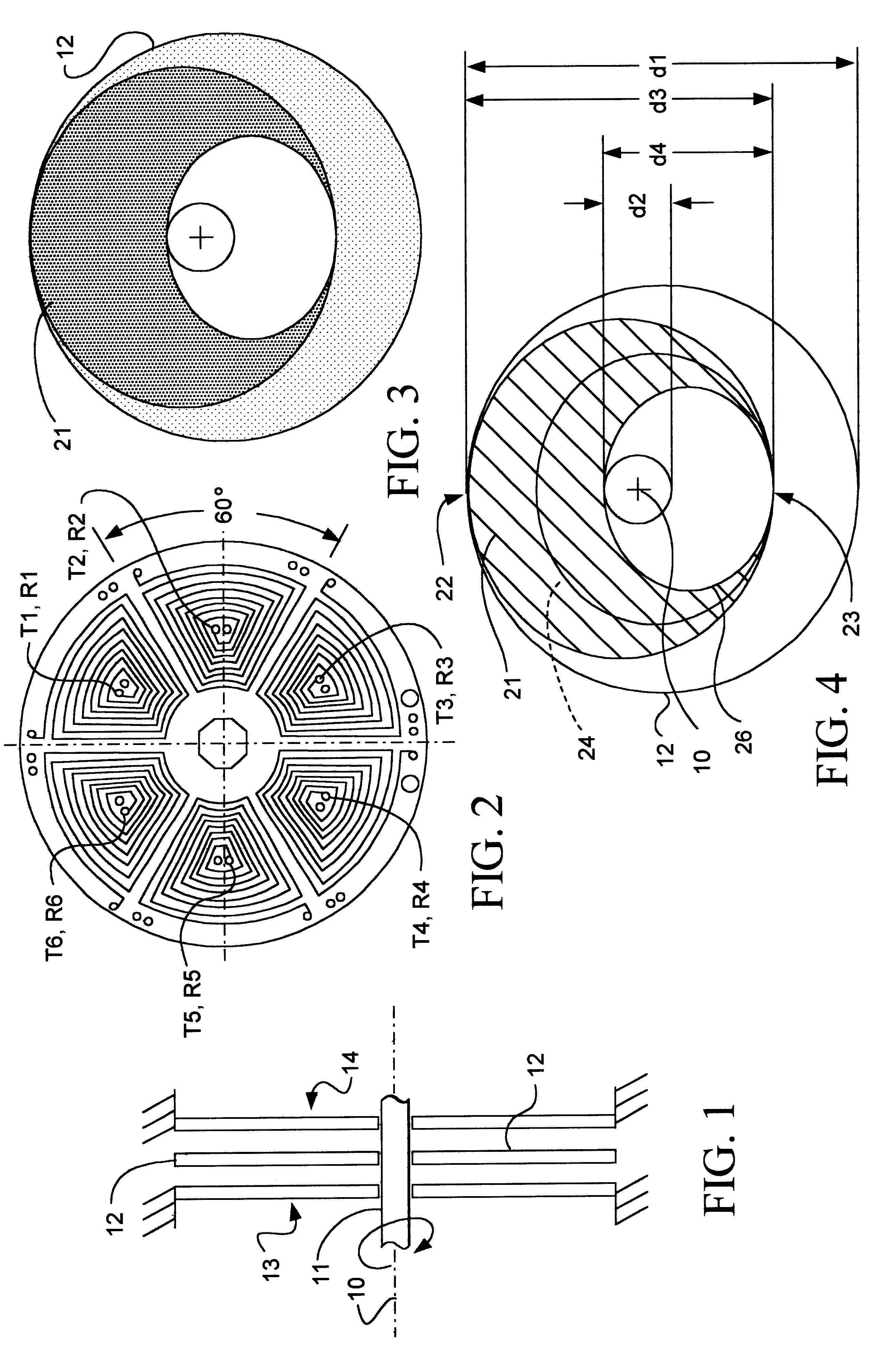
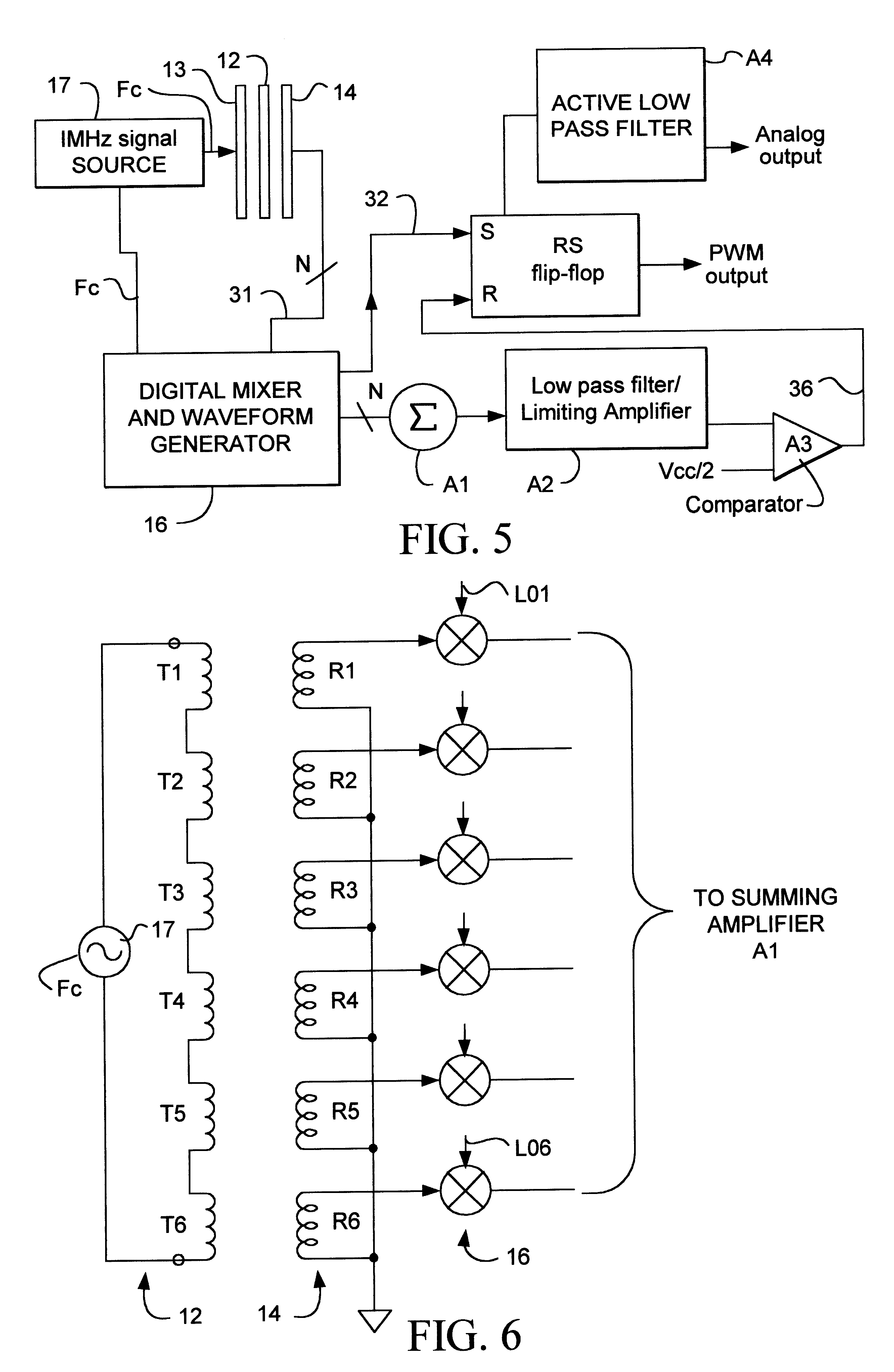
Referring now to FIG. 1 the axis 10 includes the shaft 11 on which is mounted for rotation a coupler disk 12 (also see FIG. 3). The disk is made of an insulating material such as plastic and as illustrated in FIG. 1 is interposed between a pair of substantially circular transmit and receive disks 13 and 14. These are fixed with respect to each other. FIG. 2 illustrates both disks 13 and 14 which are substantially identical. The transmit disk consists of six spiral loop antenna patterns designated T1 through T6 which are connected in a series as illustrated in FIG. 6. The receive disk 13 is also illustrated in FIG. 6 and has six identical spiral loop antenna patterns R1 through R6 with the exception that each receive coil is separately connected to a digital mixer circuit 16 a portion of which is shown. The transmit disk 12 is driven by a signal source 17 which has a frequency, F.sub.c, of 1 MHz.

Referring back to FIG. 2 both transmit and receive disks 13, 14 carry their predetermined...


PUM


Abstract

A non-contact angular position sensor has juxtaposed transmit and receive disks with a coupler disk, carrying a conductive attenuating pattern interposed therebetween. A pattern of inductive coils, which completely encircle both the transmit and receive disks have their inductive coupling individually attenuated in accordance with the angular position of the symmetrical conductive pattern on the intermediate coupling disk. The transmit disk is driven by a signal source which when received and demodulated by the receive coils and summed together provides a unique sinusoidal signal whose phase is indicative of the angular position of the intermediate coupler. The conductive pattern on the coupler is designed to provide a linear output.

Description

The present invention is directed to angular position sensor with an inductive attenuating coupler and more specifically to a non-contact type of sensor having inductively coupled transmit and receive disks with an interposed rotatable coupler.In order to meet the current stringent reliability and meantime before failure (MTBF) requirements demanded by the automotive, industrial and aerospace industries, position sensors must be based on a non-contact design approach. This is in order to minimize the wear and tear on internal components. And especially for automotive use, the design must be suited for low cost, high volume, and high reliability. One type of non-contacting sensor utilizing a so called screened inductance is illustrated in U.S. Pat. No. 4,986,124. Here a pair of drive and sense windings on the same printed circuit board have a conductive screen adjacently mounted on an axis or pin, which when rotated can "shade" the sense winding. As summarized by the above patent, it...

Claims


Application Information

Patent Timeline
Patent Type & Authority Patents(United States)
IPC IPC(8): G01D5/12G01D5/20G01B7/30G01B7/00G01D5/245
CPCG01D5/2053
Inventor MADNI, ASAD M.VUONG, JIM B.
Owner BEI SENSORS & SYST
Why Eureka
Try Eureka