Image forming apparatus having an electrically charged paper dust removing brush

a technology of paper dust removal and forming apparatus, which is applied in the direction of optics, instruments, electrographic processes, etc., can solve the problems of reducing the ability of the paper dust removal device to remove the paper dust, affecting the resultant visible image, and magnifying the problem of defective visible images

Inactive Publication Date: 2001-10-16
BROTHER KOGYO KK
View PDF1 Cites 57 Cited by
  • Summary
  • Abstract
  • Description
  • Claims
  • Application Information

AI Technical Summary

Benefits of technology

will become more apparent

Problems solved by technology

When the toner is reused during a later development process, the paper dust can degrade the resultant visible image.
The filler material can cause filming and so magnify the problem of the defective visible images.
However, because the paper-dust removing device is in contact with the photosensitive drum, the residual toner also clings to the paper-dust removing device together with the paper dust.
This will reduce the ability of the paper-dust removing device to remove the paper dust.
When a high electric voltage is applied to the conductivity-enhanced brush, however, the resistance value of the brush will decrease exponentially with respect to the applied voltage.
When an excessively high voltage is

Method used


Image

  • Image forming apparatus having an electrically charged paper dust removing brush
  • Image forming apparatus having an electrically charged paper dust removing brush
  • Image forming apparatus having an electrically charged paper dust removing brush

Examples


first embodiment

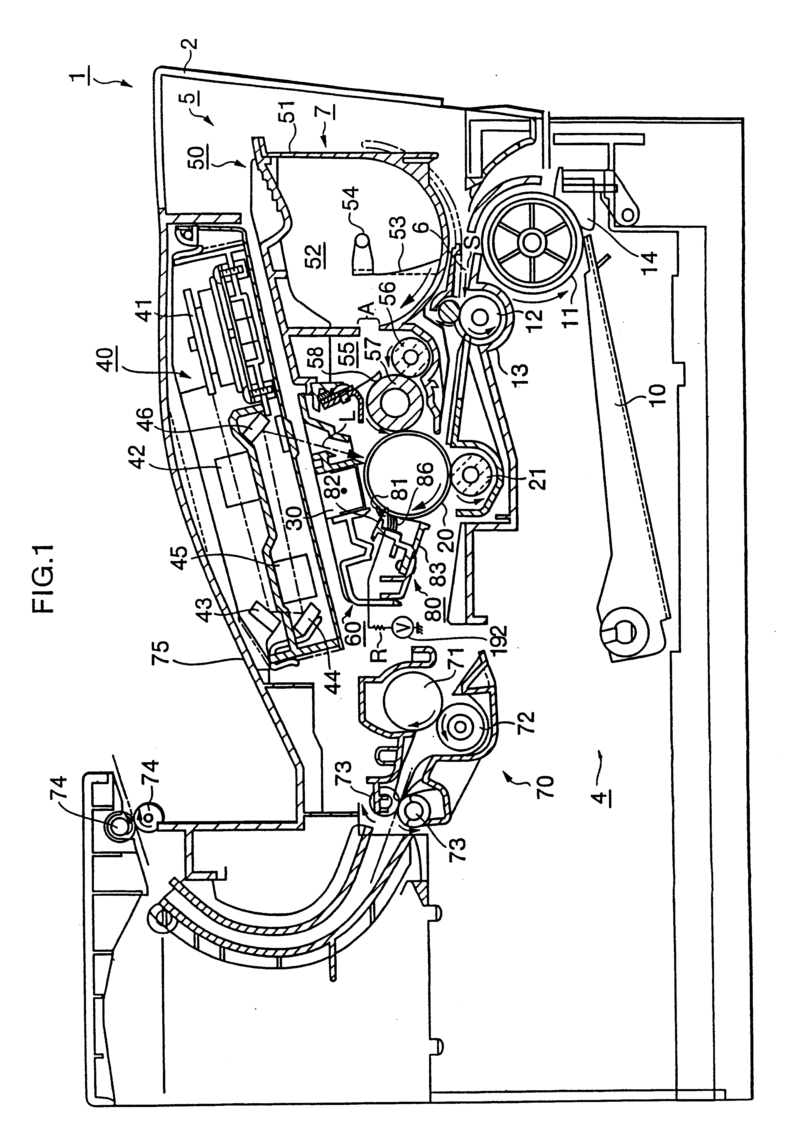
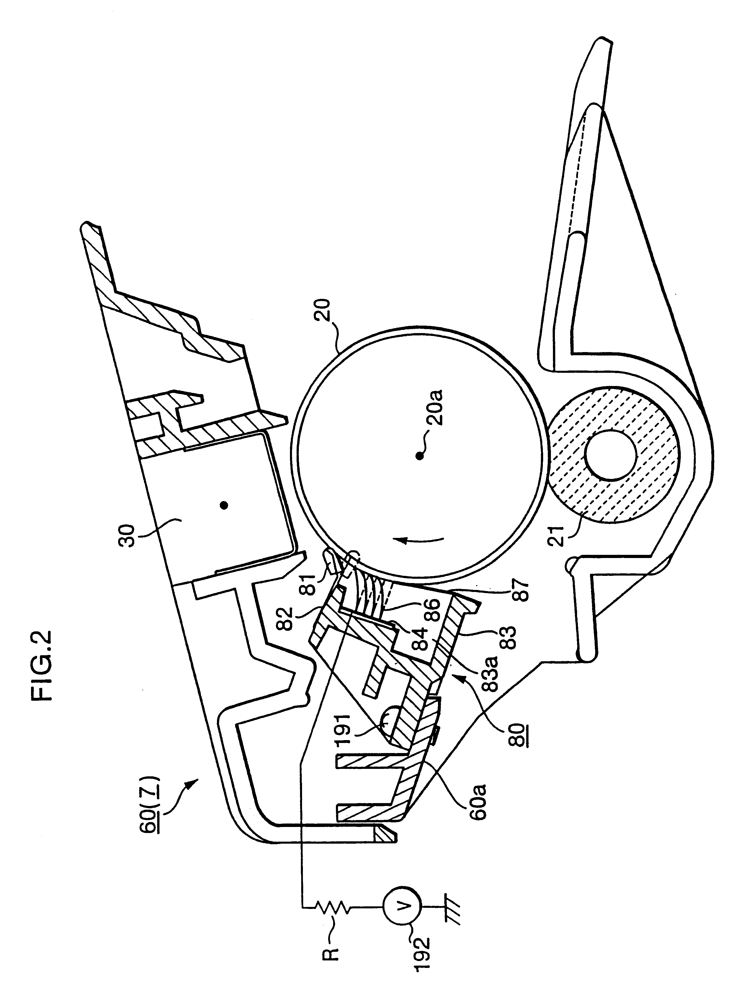
An image forming apparatus according to a first embodiment of the present invention will be described below with reference to FIGS. 1 and 2.

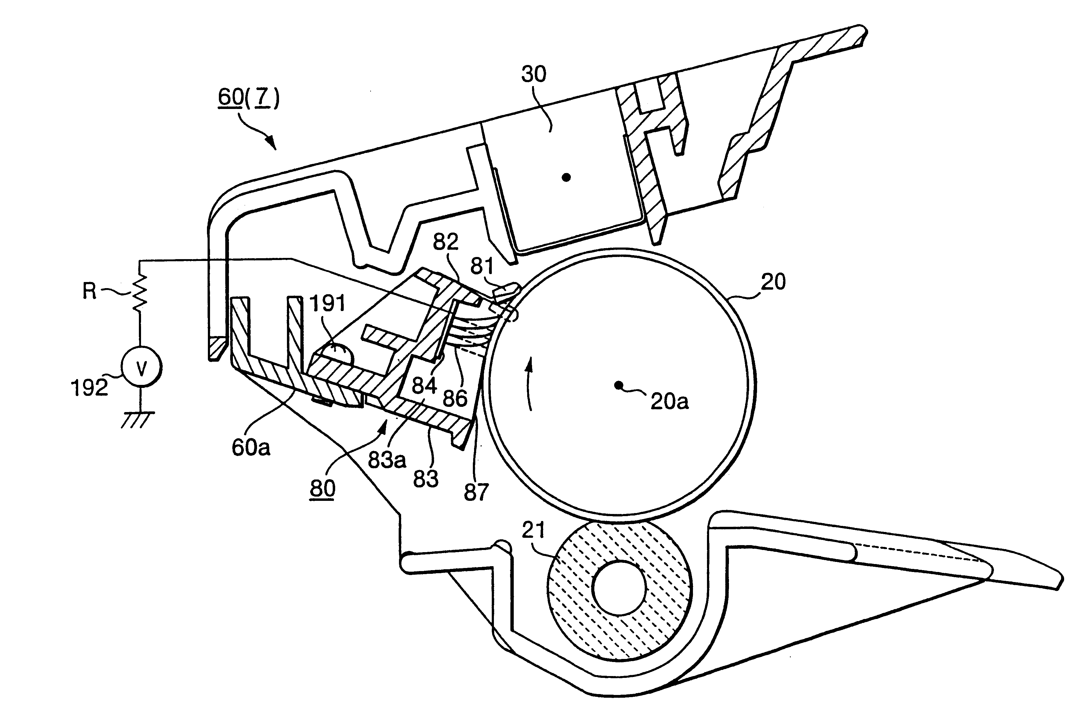
FIG. 1 is a cross-sectional view showing essential parts of a laser printer 1 that serves as the image forming apparatus according to the first embodiment. As shown in FIG. 1, the laser printer 1 includes a housing or casing 2, in which a sheet feeding unit 4 and an image printing section 5 are provided. The sheet feed unit 4 is for supplying sheets of paper P (recording medium) to the image printing section 5. The sheets of paper P serve as recording media to be printed with visible toner images. The image printing section 5 is for printing visible toner images onto the sheets of paper P.

As shown in FIG. 1, the sheet feeding unit 4 is disposed at a bottom portion of the housing 2. The sheet feeding unit 4 includes; a sheet pressing plate 10, a sheet friction-separating member 14, a sheet supply roller 11. and a pair of register rollers 12, 13. ...

second embodiment

Next, a second embodiment of the present invention will be described while referring to FIGS. 3-10. Components employed in the second embodiment having the same configuration as those of the first embodiment are designated with the same numbering.

According to the present embodiment, as shown in FIG. 3, the voltage source 192 is not mounted in the image forming apparatus 1. Instead, the charging unit 30 is used to apply an electric voltage to the brush member 86.

As shown in FIGS. 4(A) and (B), the charge unit 30 includes a shield casing 35. The shield casing 35 is supported to the wall 60a of the drum cartridge 60. The shield casing 35 is elongated in a direction parallel to the rotational axis 20a of the photosensitive drum 20. A corona wire 31 is provided within the shield casing 35. The corona wire 31 extends also in the elongated direction of the shield casing 35, that is, parallel to the rotational axis 20a of the photosensitive drum 20. The corona wire 31 is made from tungsten ...

third embodiment

Next, a third embodiment according to the present invention will be described while referring to FIG. 11. Components in the third embodiment with the same configuration as those in the first embodiment are is designated with the same numbering.

As shown in FIG. 11, the paper dust removal unit 80 of the present embodiment is provided with a brush roller 88. The brush roller 88 is constructed from a metal core and a brush member provided around the metal core. The brush member of the brush roller 88 is formed from acrylic fibers which have not been subjected to conductivity-enhancing processes so have a high resistance value. The fixed voltage source 192 applies a predetermined high voltage to the metal core of the brush roller 88.

With this configuration, potential difference sufficient for removing paper dust can be maintained between the brush roller 88 and the photosensitive drum 20. Also, discharge from the brush roller 88 to the photosensitive drum 20 can be prevented, so nonunifo...


PUM


Abstract

In an image forming apparatus, a brush member is formed from a brush made from acrylic resin that has not been subjected to conductivity-enhancing processes. The brush member is attached to a conductive plate. A resistor is provided in series with the conductive plate and a fixed power source. The fixed power source applies a predetermined high voltage to the conductive plate.

Description

1. Field of the InventionThe present. invention relates to an image forming apparatus such as a laser printer.2. Description of Related ArtLaser printers and other image forming apparatuses mainly include: a photosensitive drum, a developing roller, and a transfer roller. The photosensitive drum is formed with an electrostatic latent image on its outer peripheral surface. The developing roller is disposed in confrontation with the photosensitive drum. The developing roller supplies developing agent, such as toner, to the photosensitive drum, thereby developing the electrostatic latent image into a visible image. The transfer roller is disposed also in confrontation with the photosensitive drum. The transfer roller is applied with a transfer bias voltage with a polarity opposite to that of the photosensitive drum.Especially In non-contact type printers, a charger uniformly charges the outer peripheral surface of the photosensitive drum. A laser generating unit modulates a laser beam ...

Claims


Application Information

Patent Timeline
IPC IPC(8): G03G21/00
CPCG03G21/0005G03G21/0064G03G2221/0005G03G2221/0057G03G2221/0063G03G2221/0089
Inventor NISHIMURA, SOICHIROFUWAZAKI, TAKESHI
Owner BROTHER KOGYO KK
Why Eureka
Try Eureka