Railway vehicle bogie and process for manufacturing a side member of such a bogie

a technology for rail vehicles and side parts, which is applied in the direction of axle-box mounting, rail engagement elements, transportation and packaging, etc., can solve the problems of not enabling forces, not allowing the assembly of accessories or safety elements, and efficiently absorbing

Inactive Publication Date: 2001-10-23
ALSTOM TRANSPORT TECH SAS
View PDF10 Cites 55 Cited by
  • Summary
  • Abstract
  • Description
  • Claims
  • Application Information

AI Technical Summary

Benefits of technology

In addition, the particularly simple geometry of the side member leads to an attractive cost, which improves the overall economic performances of the bogie.
According to a first advantageous embodiment of the invention, the elastic blade is made of composite material based on fiber-reinforced plastics resin. In that case, the bogie made is substantially lighter than the conventional steel devices, this making it possible to increase the load embarked on the vehicle. The suppleness of a composite material enables it to provide efficient damping at the vibratory frequences most often active in a bogie. In addition, a bogie made of composite material according to the invention may be manufactured more easily than a conventional bogie, particularly due to its simple geometry. The composite material may be based on epoxide, phenolic or other resin and reinforced with glass, carbon, aramid and / or other specific fibers allowing a possible failure of the material to be detected.
According to another embodiment of the invention, the elastic blade may be made of metal, preferably spring steel. This second embodiment makes it possible to use a conventional material whose properties are well known in the field of railway construction.
According to another advantageous aspect of the invention, the projecting part comprises two substantially opposite surfaces against which corresponding surfaces of the elongated webs of the elastic blade are adapted to abut. This geometry of the projecting part and of the elastic blade avoids a pivoting of the blade around the projecting part, which improves fixation between these two elements.
According to an advantageous aspect of the process of the invention, said process consists in adapting the distance between the studs as a function of the wheel base and / or the load provided on the side member. According to another advantageous aspect, the process consists in adapting the number of winding turns of the lap around the studs as a function of the dimensions and / or the rigidity provided for the side member. The process of the invention is very adaptable to the operational characteristics of the side member, with the result that several types of side members may be manufactured in the same installation, which is particularly advantageous from the industrial standpoint.

Problems solved by technology

These webs do not enable the forces due to the vertical and transverse accelerations of the equipment in motion to be efficiently absorbed and do not allow the assembly of accessory or safety elements such as a motor, a braking system or a control system.
This would increase the cost of the bogie and might raise technical problems of molding.
In addition, the particularly simple geometry of the side member leads to an attractive cost, which improves the overall economic performances of the bogie.

Method used


Image

  • Railway vehicle bogie and process for manufacturing a side member of such a bogie
  • Railway vehicle bogie and process for manufacturing a side member of such a bogie
  • Railway vehicle bogie and process for manufacturing a side member of such a bogie

Examples


second embodiment

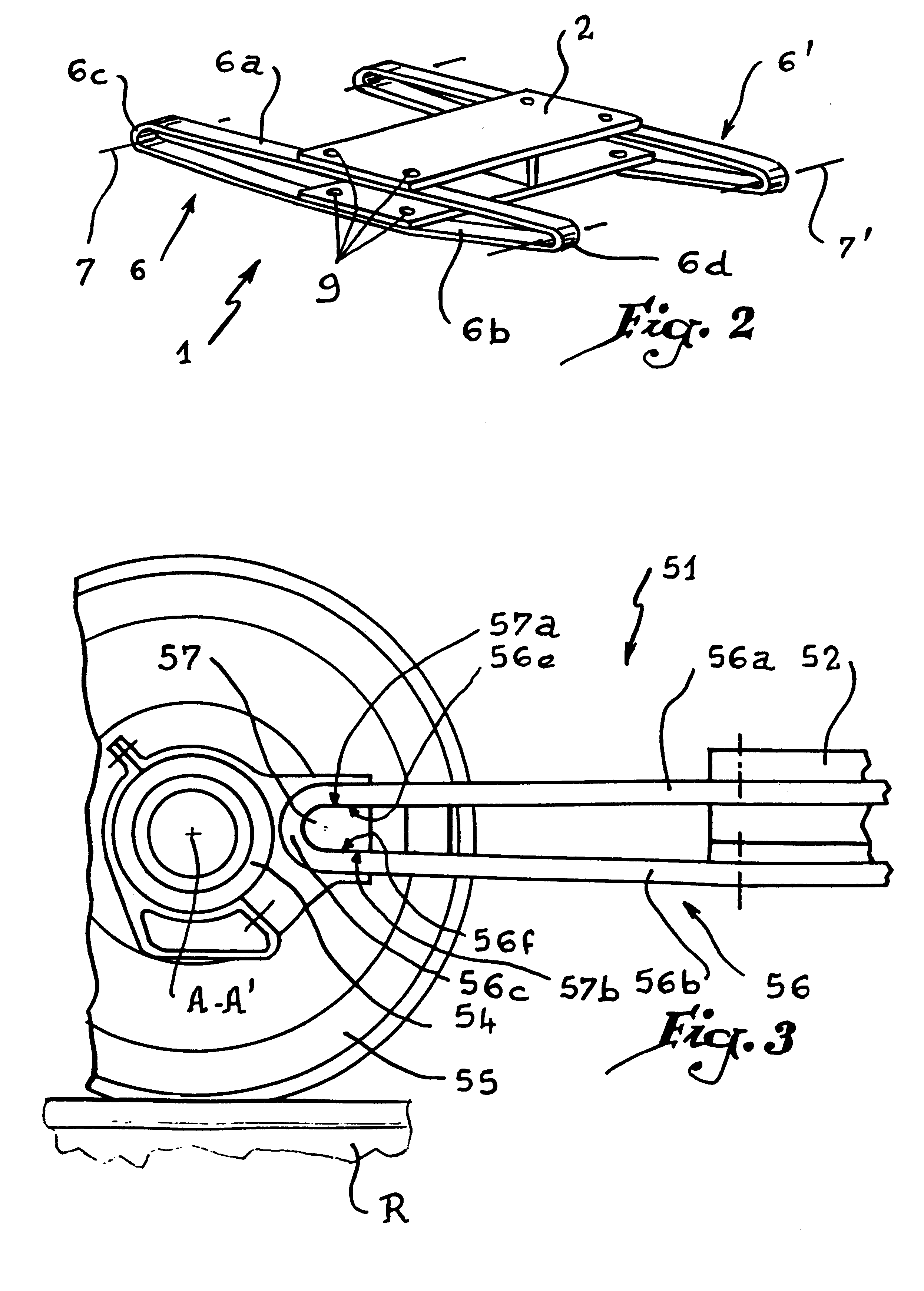
In the invention shown in FIGS. 3 and 4, elements similar to those of the embodiment of FIGS. 1 and 2 bear identical references increased by 50. In this embodiment, a bogie 51 comprises a chassis 52 supporting a suspension assembly (not shown), while side members, of which only one, referenced 56, is visible in FIGS. 3 and 4, are taut between the chassis 2 and the axle boxes, of which only one, referenced 54, is visible, this axle box defining an axis of rotation A-A' of wheels 55.

The side member 56 is made of spring steel and comprises an upper web or tie 56a and a lower web or tie 56b connected by two curved zones, of which only one, referenced 56c, is visible. The curved zone is disposed around a projecting part 57 of the axle box 54 on which it is mechanically fixed. More precisely, the projecting part 57 is in the form of a heel and comprises an upper surface 57a and a lower surface 57b which are substantially plane, against which corresponding surfaces 56e and 56f belonging re...

first embodiment

A damper such as an elastomer block might, of course, also be used with the device of the invention shown in FIGS. 1 and 2. Similarly, the geometry of the heel 57 is transposable with a bogie made of composite material.

Manufacture of a side member made of composite material, particularly of the type shown in FIGS. 1 and 2, is described with reference to FIGS. 5 and 6.

Two studs 101 and 102 are mounted on a plate 103 and their distance E is adjusted as a function of the dimensions desired for the side member to be manufactured. When this distance has been adjusted, a continuous lap 104 of glass fibers is wound around these two studs 101 and 102 over at least one turn, preferably over a large number of turns so as to constitute a closed loop 105. This loop is resistant from the mechanical standpoint, as the reinforcing fibers extend over the whole length of the loop. When several turns have been made, as shown in FIG. 6, it is possible to dispose the assembly thus formed inside an oven...


PUM


Abstract

A railway vehicle bogie, including at least two axles, at least one side member being provided to connect the axles to a central part of the bogie. The side member is formed by an elastic blade shaped as a vertically oriented continuous flattened loop which may be made of composite material or of metal. A process for manufacturing a side member of composite material consists in winding a continuous lap of reinforcing fibers over at least one turn around two studs so as to form a loop, and polymerizing a resin-based matrix around the fibers.

Description

1. Field of the InventionThe present invention relates to a railway vehicle bogie and to a process or manufacturing a side member for such a bogie.2. Description of the Related ArtA railway vehicle bogie is intended to support a vehicle, such as a car body or motor car body, on a plurality of wheels supported on axles. Taking into account the masses of the car bodies or motor car bodies and their speed of movement, the forces due to accelerations of this stock, particularly during changes of direction, are considerable, with the result that it is usual to produce bogies in the form of massive parts made of steel or of welded structure. These massive pieces and welded structures are rigid and must be equipped with suspension and damping systems to ensure comfort for passengers or the absorption of vibrations due to irregularities of track on which the stock moves.European Patent Application 0 031 008 discloses a railway vehicle bogie comprising H-shaped webs made of composite materia...

Claims


Application Information

Patent Timeline
Patent Type & Authority Patents(United States)
IPC IPC(8): B61F5/30B61F5/32B61F5/52B61F5/00
CPCB61F5/302B61F5/325B61F5/52B61F5/523Y02T30/38Y02T30/00
Inventor LANDROT, ALAIN
Owner ALSTOM TRANSPORT TECH SAS
Why Eureka
Try Eureka