
Multi-patient fluid dispensing

a fluid dispensing and multi-patient technology, applied in intravenous devices, process and machine control, instruments, etc., can solve the problems of pressure drop through the filter, volume of fluid remaining in the filter, and no way to verify that the filter is not leaking, so as to minimize the chance of cross-contamination

Inactive Publication Date: 2001-10-23
BAJER MEDIKAL KEHA INK
View PDF138 Cites 140 Cited by
  • Summary
  • Abstract
  • Description
  • Claims
  • Application Information

AI Technical Summary

Benefits of technology

It is a principal object of this invention to provide an improved apparatus for injecting a fluid medium into a plurality of patients while minimizing the chance of cross-contamination.
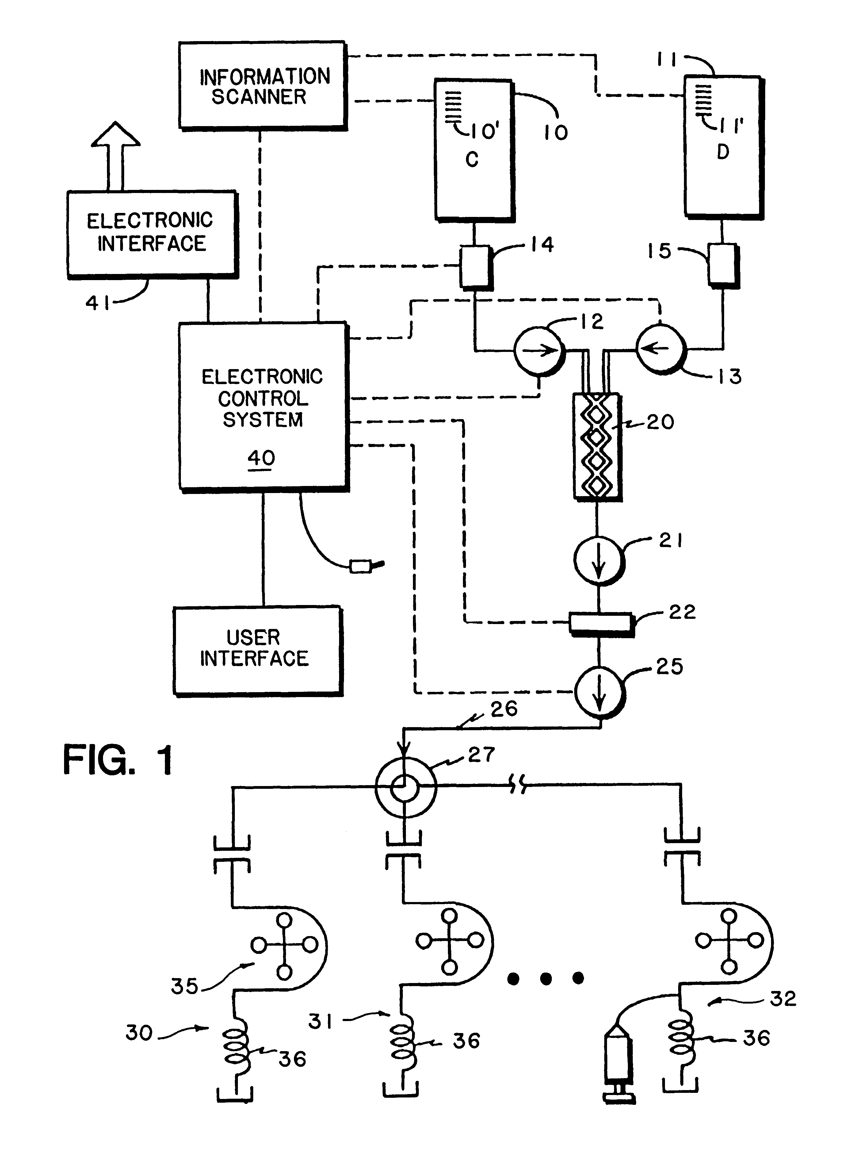
FIG. 1 diagrammatically shows an apparatus and a system for injecting a fluid medium directly into a patient which minimizes the chance of patient-to-patient cross-contamination;

Problems solved by technology

Viruses and proteins can penetrate the filter but are not active, and so cannot swim upstream.
The drawbacks to this approach involve the pressure drop through the filter and volume of fluid remaining in the filter.
Also, there is no way to verify that the filter is not leaking.

Method used


Image

  • Multi-patient fluid dispensing
  • Multi-patient fluid dispensing
  • Multi-patient fluid dispensing

Examples


second embodiment

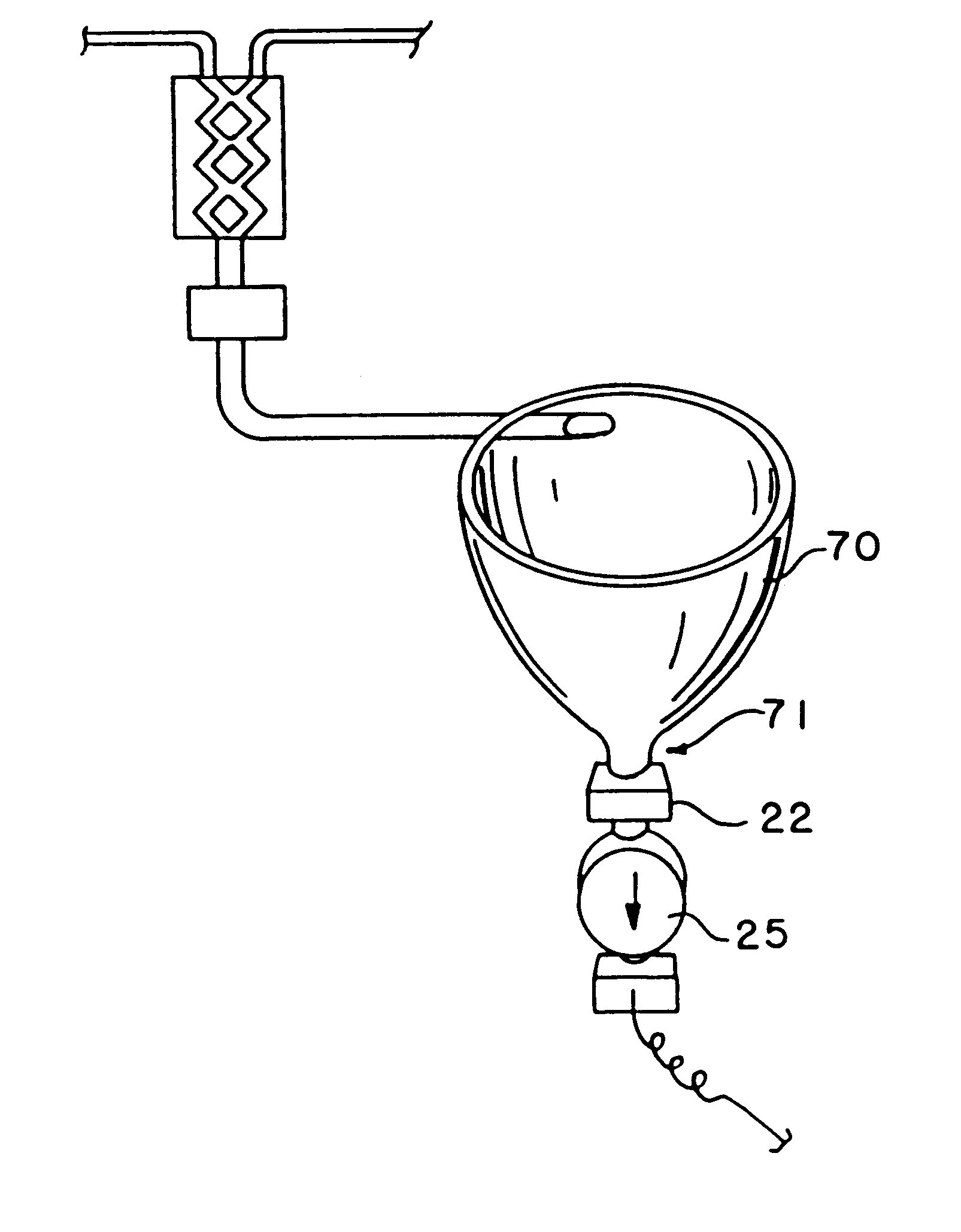
A second embodiment for the class of blocking means forming a break in the fluid stream uses a collapsible bag 75, as shown in FIG. 7, or other large container instead of the funnel. Operation is a little different. When the arm sequence is initiated, a significant fraction of the fluid requested for the injection is pumped into the collapsible bag. This fraction could be operator controlled and depend upon the confidence the operator had that the full amount of fluid will be used. When the operator depresses the start switch, the injection starts. The metering pumps continue filling the bag at a slower rate than the pressurizing pump is withdrawing it, with the fill rate chosen so that filling is completed a few seconds before the injection is completed. The benefit of this over the funnel is the ability to start the injection and change flow rates instantaneously. The bag may be less costly than the funnel though neither part sees high pressures. A final benefit may be user percep...


PUM


Abstract

A system for delivering sterile fluid to a patient, while preventing cross-contamination, in which flow interrupting means are provided which basically create regions where no fluid exists in the comprehensive or over-all quality of material that is flowing from a fluid source to a patient.

Description

In copending application Ser. No. 08 / 144,845 of even date herewith and assigned to the same Assignee as the present invention, discussion was undertaken with regard to the problems arising from the potential cross-contamination that can occur with a multi-patient fluid dispensing system. One facet of the system provided involves prevention of contamination of the multi-use segment of the fluid path during the time the system is connected to the patient. The disclosed system utilized one of two methods: a back flow preventing valve and a sterile filter, or a physical separation achieved by filling a dose container and separating the dose container from the filling fluid path before connection to the patient.A back flow valve and a sterile filter combination should give sufficient protection. Bacteria cannot penetrate the filter. Viruses and proteins can penetrate the filter but are not active, and so cannot swim upstream. They can only diffuse. The drawbacks to this approach involve ...

Claims


Application Information

Patent Timeline
Patent Type & Authority Patents(United States)
IPC IPC(8): A61M5/168
CPCA61M5/16827
Inventor UBER, III, ARTHUR E.
Owner BAJER MEDIKAL KEHA INK
Learn More