Laser alignment system

a laser alignment and laser technology, applied in the field of laser alignment systems, can solve the problems of not being able to quantify, unable to disclose the quantification of misalignment, and unable to meet the requirements of the application,

Inactive Publication Date: 2001-10-30
PINPOINT LASER SYST
View PDF31 Cites 41 Cited by
  • Summary
  • Abstract
  • Description
  • Claims
  • Application Information

AI Technical Summary

Problems solved by technology

Such a system seems to require multiple detectors that can become costly to implement.
While such a system does provide some indication of surface flatness, it appears it will only detect extensions of the surface into the beam.
Moreover, this system does not appear to quantify any misalignment.
Nothing in this patent discloses any quantification of misalignment.
For example, the Smith-Vaniz patent seems directed primarily to moving an object to a particular location, but does not seem readily adapted to measure surface flatness.
Moreover, such alignment systems generally require a trained operator.
Given the single-purpose designs and requirements for training and the expense of such systems, many companies can not afford to purchase such equipment and employ such individuals on a full-time basis.
The use of subcontractors oftentimes introduces scheduling problems and intolerable delays which further increases the costs of the alignment procedure.

Method used


Image

  • Laser alignment system
  • Laser alignment system
  • Laser alignment system

Examples


Embodiment Construction

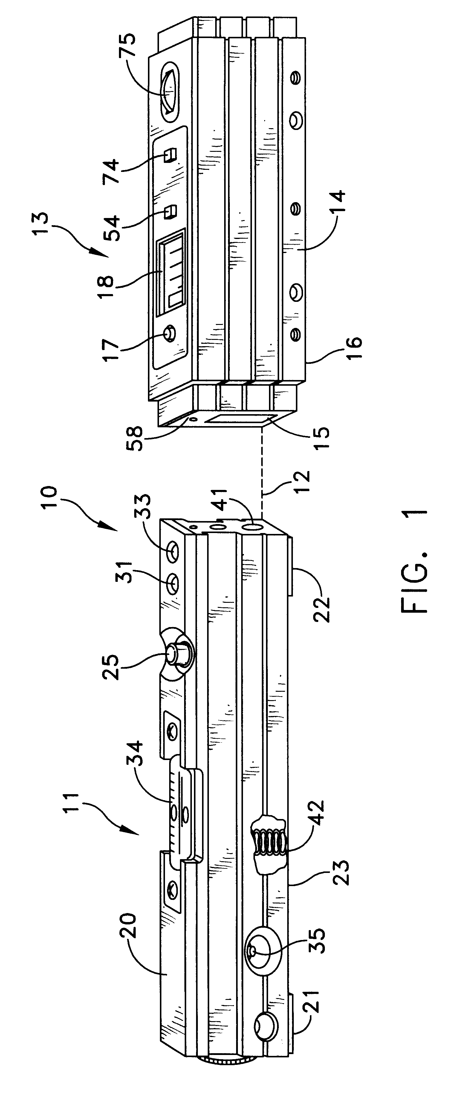
FIG. 1 depicts an alignment system 10 constructed in accordance with this invention. The system 10 includes a transmitter 11 that projects a laser beam 12 along a projection axis. A receiver 13 is positioned to intercept the laser beam and includes a housing 14 with a detector window 15. A bottom portion 16 formed with flat machined edges or surfaces. These edges or surfaces define a receiver reference plane that is oriented horizontally in FIG. 1.

When the receiver 13 is energized, the laser beam strikes an internal detector described later. When the laser beam is in a prescribed range of locations on the detector, a light 17 indicates that receipt by changing to a green color. At that point a visual annunciator in the form of a multiple numeric character display 18 provides a reading of the deviation of the reference plane from the laser beam 12, as will now be described in more detail.

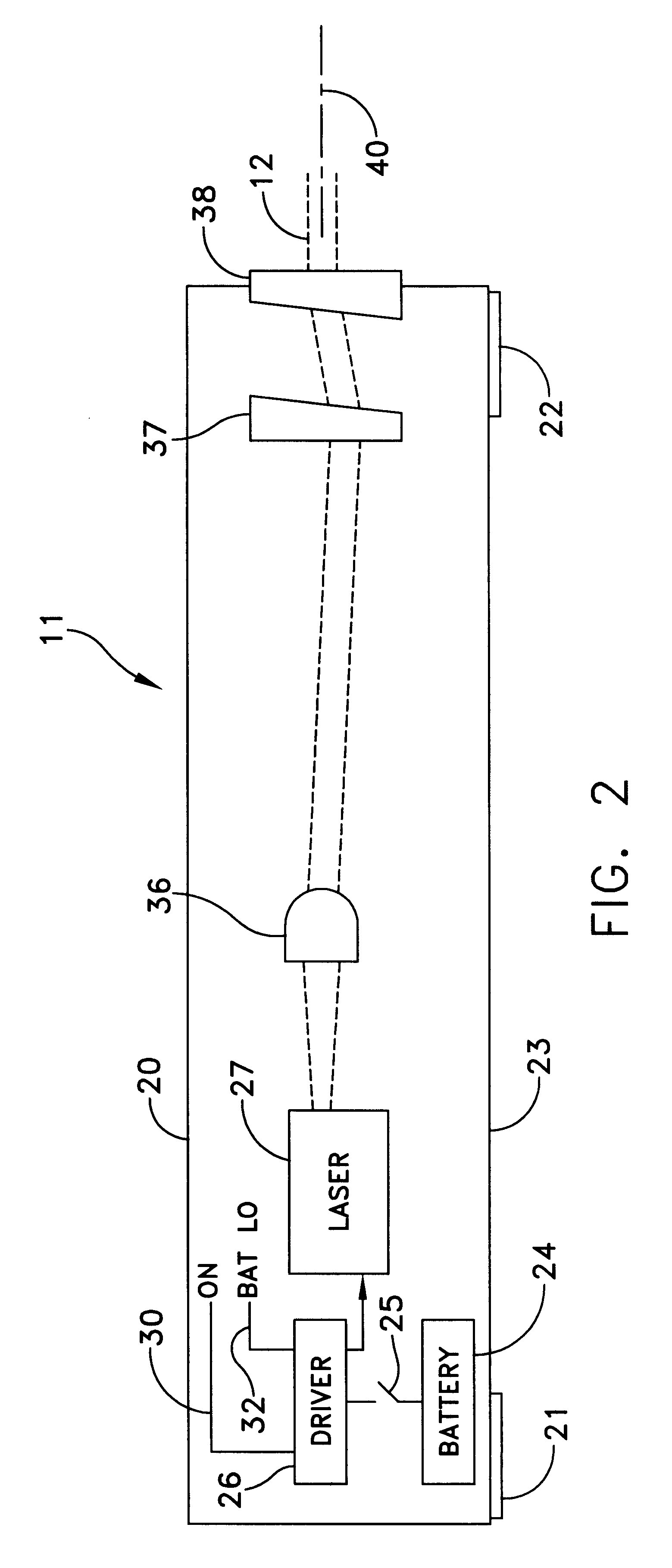
FIGS. 1 and 2 depict the transmitter 11 as including a housing 20. In this particular embodiment ...


PUM


Abstract

An alignment system includes a laser transmitter and receiver. The receiver includes a linear photodetector array centered at a predetermined location with respect to machined surfaces that define a receiver reference plane. An indicator on the receiver displays a deviation of the position of the laser beam from a predetermined location on the photodetector array thereby to quantify any misalignment of a surface supporting the receiver with respect to the transmitted laser beam.

Description

1. Field of the InventionThis invention generally relates to apparatus for aligning objects and more particularly to a portable system utilizing a laser for enabling an operator to quantify alignment and misalignments precisely.2. Description of Related ArtThere are a number of applications where it is important to obtain precise alignment between two elements or among three or more elements and particularly to quantify any misalignments that may exist. Examples in which such alignments are beneficial include aligning two or more machine elements, such as machine beds or shafts to a common plane or axis. Another example includes measuring surface flatness to ascertain any variance of a surface from a common plane.The need for such alignment applications has led to the development of different apparatus specifically designed for an application. U.S. Letters Pat. No. 3,603,688 (1971) to Smith-Vaniz depicts an alignment apparatus with a laser light source and a remote target object. Th...

Claims


Application Information

Patent Timeline
Patent Type & Authority Patents(United States)
IPC IPC(8): G01C15/00
CPCG01C15/004Y10S33/21
Inventor CREIGHTON, III, ALBERT M.
Owner PINPOINT LASER SYST
Why Eureka
Try Eureka