Fluid-filled capacitor with pressure interrupter means and internal compressible air chamber

a capacitor and pressure interrupter technology, applied in the field of capacitors, can solve the problems of high internal pressure within the housing, inability to completely immerse the capacitive element in the insulating fluid, and inability to produce heat and outgassing, and achieve the effect of facilitating the operation of the pressure responsive interrupter means

Inactive Publication Date: 2001-11-06
AMERICAN RADIONIC CO INC
View PDF7 Cites 79 Cited by
  • Summary
  • Abstract
  • Description
  • Claims
  • Application Information

AI Technical Summary

Benefits of technology

In further carrying out the invention, operation of the pressure responsive interrupter means is facilitated by confining a compressible volume of a

Problems solved by technology

If the capacitive element fails, it may do so in a sudden and violent manner, producing heat and out-gassing such that high internal pressures are developed within the housing.
However, one of the major drawbacks of leaving air space in this type of capacitor is that the capacitive element may not be totally immersed in the insulating fluid.
When the insulating fluid does not fully cover the capacitor element, at least a portion the end spray area of the capacitive element

Method used


Image

  • Fluid-filled capacitor with pressure interrupter means and internal compressible air chamber
  • Fluid-filled capacitor with pressure interrupter means and internal compressible air chamber
  • Fluid-filled capacitor with pressure interrupter means and internal compressible air chamber

Examples


Embodiment Construction

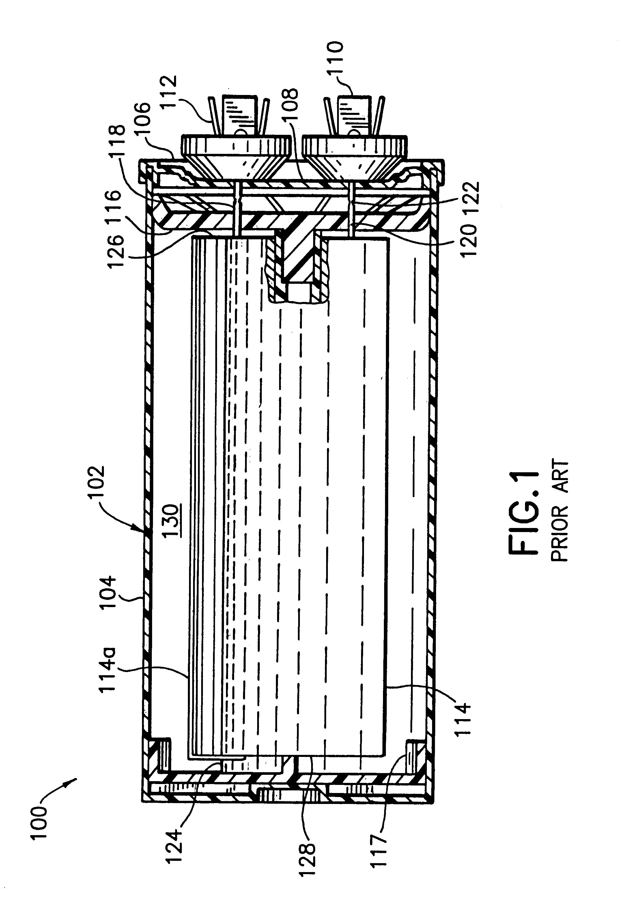
With reference to FIG. 1, there is shown a prior art capacitor 100 deployed on its side in a horizontal position, as it may be installed. The prior art capacitor 100 comprises a polymer housing 102 having a cylindrical case 104 and a cover 106. The cover 106 has a recessed central panel 108, on which terminals 110 and 112 are mounted.

A capacitive element 114 is positioned in the case 104, and is spaced from the cover 106 by a top retainer 116 so that the capacitive element is held down with respect to the cover. A spider 117, which is not liquid-tight with respect to the case 104, centers the opposite end of the capacitive element 114. The capacitive element is connected to the terminals via wire leads 118 and 120, wire lead 120 being substantially in tension and nicked at 122 to provide a weak point. The combination of the nicked wire lead, the recessed cover panel 108 and the top retainer 116 form a pressure responsive interrupter system for the capacitor 100. Upon an over pressur...


PUM


Abstract

A capacitor has a polymer housing and a wound metallized film capacitive element received in the housing, with leads connected to terminals on the cover of the housing through a pressure responsive interrupter assembly. An air chamber is provided in the housing, confining a compressible volume of air, and insulating fluid fills the remaining volume of the housing, substantially immersing the capacitive element. The air chamber is advantageously defined by a piston slidably mounted in the housing. Upon a high pressure condition caused by failure of the capacitive element, the volume of air is compressed to cushion the onset of the high pressure, protecting the case from rupture prior to operation of the pressure responsive interrupter assembly.

Description

The invention herein relates to a capacitor having a capacitive element in a housing and insulating fluid surrounding the capacitive element, a pressure responsive interrupter means, and a volume of compressible air confined within the housing which facilitates operation of the pressure responsive interrupter means.BACKGROUND OF INVENTIONCapacitors of the type typically used in motor run applications have a housing and a capacitive element of wound polymer film within the housing. The housing is at least partially filled with an insulating fluid. The capacitive element is connected to terminals on the exterior of the housing, and a pressure responsive interrupter system is associated with the terminals and conductors connecting the capacitive element with the terminals. If the capacitive element fails, it may do so in a sudden and violent manner, producing heat and out-gassing such that high internal pressures are developed within the housing. The pressure responsive interrupter sys...

Claims


Application Information

Patent Timeline
IPC IPC(8): H01G4/002H01G2/12H01G2/14H01G2/18H01G2/22H01G5/00H01G5/019H01G4/255H01G2/00
CPCH01G2/14
Inventor STOCKMAN, ROBERT M.STOCKMAN, RICHARD W.ZACHERL, DEAN T.
Owner AMERICAN RADIONIC CO INC
Why Eureka
Try Eureka