Valve connector

a valve connector and valve technology, applied in the direction of positive displacement liquid engines, couplings, machines/engines, etc., can solve the problems of many people's problems in inflating tyres, and achieve the effect of convenient use, convenient inflating of tyres, and convenient driving for users

Inactive Publication Date: 2001-11-13
NVB INT AS
View PDF42 Cites 18 Cited by
  • Summary
  • Abstract
  • Description
  • Claims
  • Application Information

AI Technical Summary

Benefits of technology

With a valve connector according to claim 1 equipped with such automatic sliding activating pin it is possible to mount the valve connector equipped with a valve to a compressor hose, which can be available to the public known. e.g. from bicycle shops, etc. There, it is not necessary to fasten the valve connector to the valve, as the user excerts the pressure necessary to secure an airtight connection.
With such valve connector, inflating tyres without the user having to identify the valve type and functioning has become possible. The operation conveniency has also increased significantly, and it will now be easier for the user to inflate the tyre to the correct pressure, which in general eases the driving and redu

Problems solved by technology

Inflating a tyre is a problem to many people, especially if the t

Method used


Image

  • Valve connector
  • Valve connector
  • Valve connector

Examples


Embodiment Construction

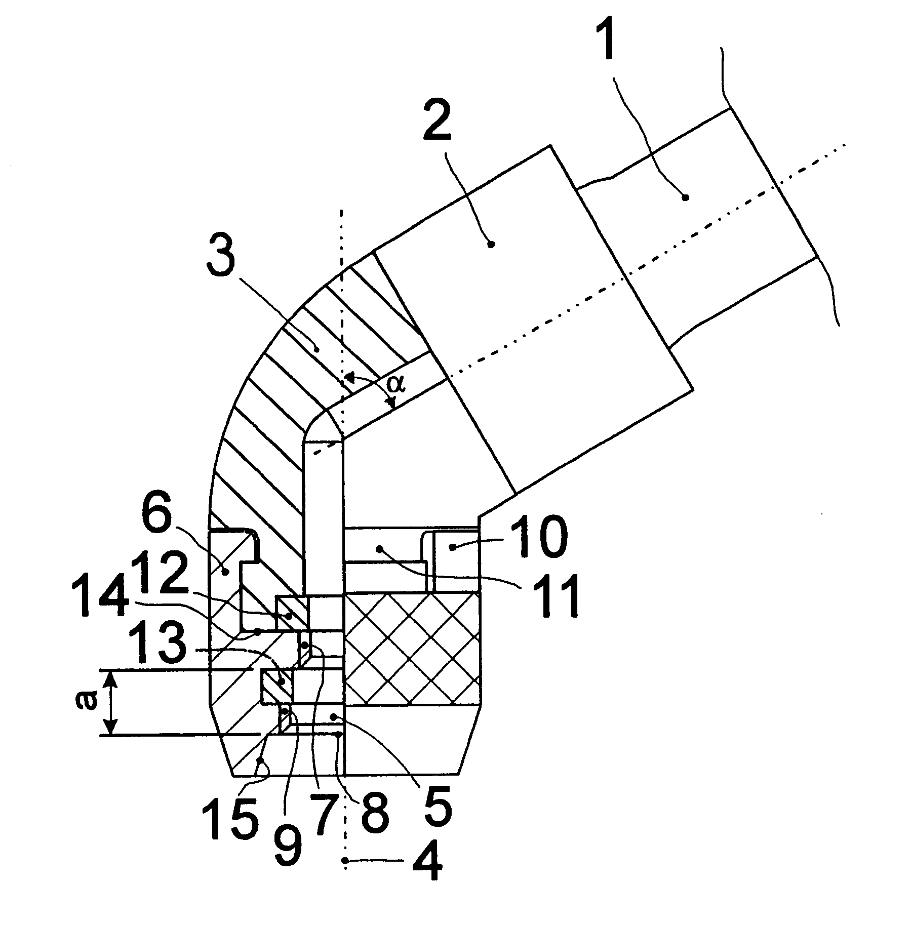
In FIG. 1 the pump hose 1 is mounted on the housing 3 by means of the ring clamp 2. The housing 3 is bent in an angle of e.g. 30.degree.-60.degree. in relation to the centre line 4 of coupling hole 5. The bushing 6 is in the shown embodiment equipped with two ISO thread types: 5V2 thread 7 starting farthest from the opening 8 of the coupling hole 5 and 8V1 thread 9 starting at the abovementioned opening. At (dis-)connection, the bushing 6 is turned around and is kept in the grooves 11 of the housing 3 by means of grip-hooks 10. The gasket seals 12 and 13 are tightening against the thread types 5V2 and 8V1. The gasket seal 12 is also tightening the crossing 14 between the housing 3 and the bushing 6 when the connector is used on a Schrader valve. The underside of the bushing 6 is equipped with a taper 15.

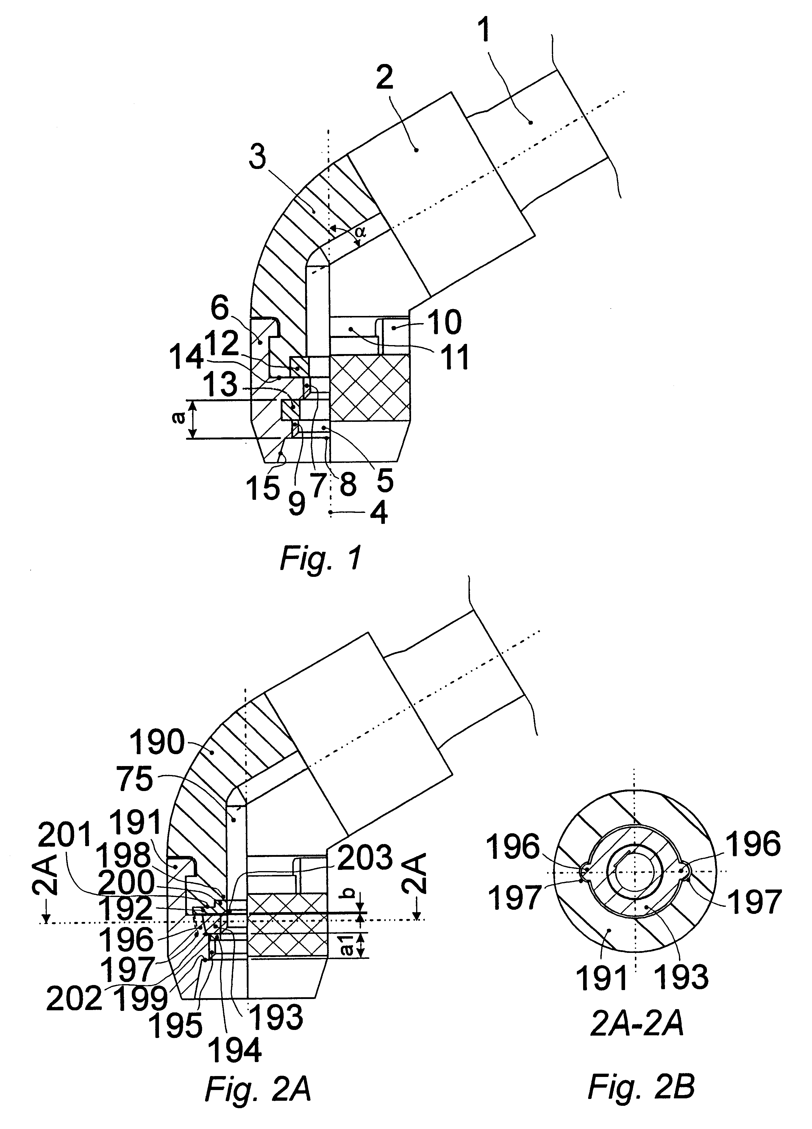
FIG. 2A shows a second embodiment. The housing 190 is equipped with a coupling bushing 191, which freely and without friction can turn around the housing 190 because of the small spa...


PUM


Abstract

By a universal valve connector for inflation valves of vehicle types (Sclaverand, Dunlop-Woods, or Schrader), whose connector consists of a connector housing (368), which partly is connected to a pressure source, preferably a hand or foot pump, and which partly has a coupling hold (5) with a diameter corresponding to the diameter of the valve, which is to be connected, where the coupling hole is equipped with a securing means for securing on the valve, plus a sealing means against valves of different sizes. This is achieved by the sealing means (366) being mounted coaxially in the connector housing (368) and being established on at least two parallel, separate levels, having the centre line (4) of the connector housing (368), which is coaxial to the centre line of the valve, as its normal, where the minor diameters of the sealing means approximately correspond to the major diameter of the current valve dimensions, on which the connector is mounted when used, that the sealing means (366), closest to the opening (8) of the coupling hole (5) in the connector housing (368) has the biggest minor diameter, while the sealing means (366) farthest from the opening (8) of the coupling hole in the connector housing (368) has the smallest minor diameter, and diameters between the extremes are lying corresponding separate distance between these extremes. The valve connector has the possibility of automatically adjust itself to the valve in question and if needed to activate the central core of a Schrader valve. Also, it is possible to use the connector with existing pumps.

Description

The invention concerns a valve connector for inflation through varying valves of vehicle types.For reasons of clarity, some of the standards used will be cited. In the ISO standard No. 10475:1992(E). thread for tyre inflation valves of vehicles is described. The most used threads are designated 5V2 (DIN: Vg 5,2), which has a nominal diameter of 5.2 mm and a pitch of 1.058 mm, and 8V1 (DIN: Va 8), which has a nominal diameter of 7.7 mm and a pitch of 0.794 mm respectively. These thread types are used in the valve types of Dunlop-Woods, Sclaverand or Schrader. The last mentioned valve type is frequently used on common cars. where a spring-loaded pin head in the valve core must be kept down in preparation of the passage of air, while pumping a tyre. For this purpose, the valve connector must be equipped with suitable means which can serve this aim. Moreover, suitable means, e.g. a contra valve or the like, must be used to ensure a that loss of air is avoided when activating the valve c...

Claims


Application Information

Patent Timeline
IPC IPC(8): B60S5/04B60S5/00F16L37/20F16L21/02F16L37/00F16L21/04B60C29/00F04B33/00F04B23/00F04B41/00F16K15/20
CPCB60S5/04F16L21/04F16L37/20Y10T137/3584Y10T137/0318Y10T137/36Y10T137/3724F04B33/00
Inventor VAN DER BLOM, NICOLAAS
Owner NVB INT AS
Why Eureka
Try Eureka