Method and apparatus for image stabilization in display device

Inactive Publication Date: 2001-11-13
IBM CORP
View PDF21 Cites 75 Cited by
  • Summary
  • Abstract
  • Description
  • Claims
  • Application Information

AI Technical Summary

Problems solved by technology

In a moving vehicle such as an automobile, a disadvantage of viewing, for example, a laptop computer's display, such as for the IBM Thinkpad.RTM., is the eye strain caused by vibrations and jitter of the vehicle.
Further, the observer cannot easily follow the image during such vibration/jitter of the vehicle.
Additionally, there are certain human diseases which manifest themselves in tremors or palsy which induce movement in the device that make it nearly impossible for the handicapped user to view the display.
However, s

Method used


Image

  • Method and apparatus for image stabilization in display device
  • Method and apparatus for image stabilization in display device
  • Method and apparatus for image stabilization in display device

Examples


Example

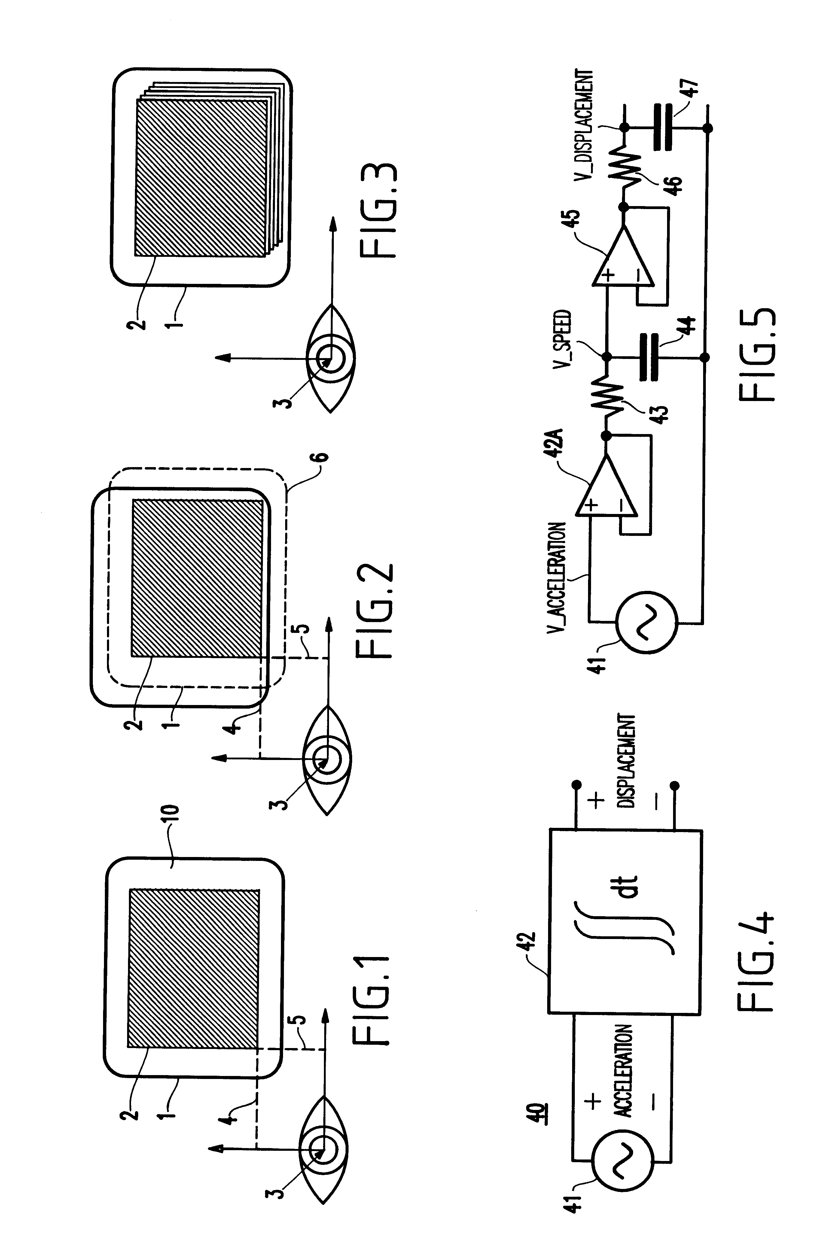
Referring now to the drawings, and more particularly to FIGS. 1-8E, there are shown preferred embodiments and modifications thereto of the method and structures according to the present invention. The same components in the Figures are designated with the same reference numerals for ease of understanding.

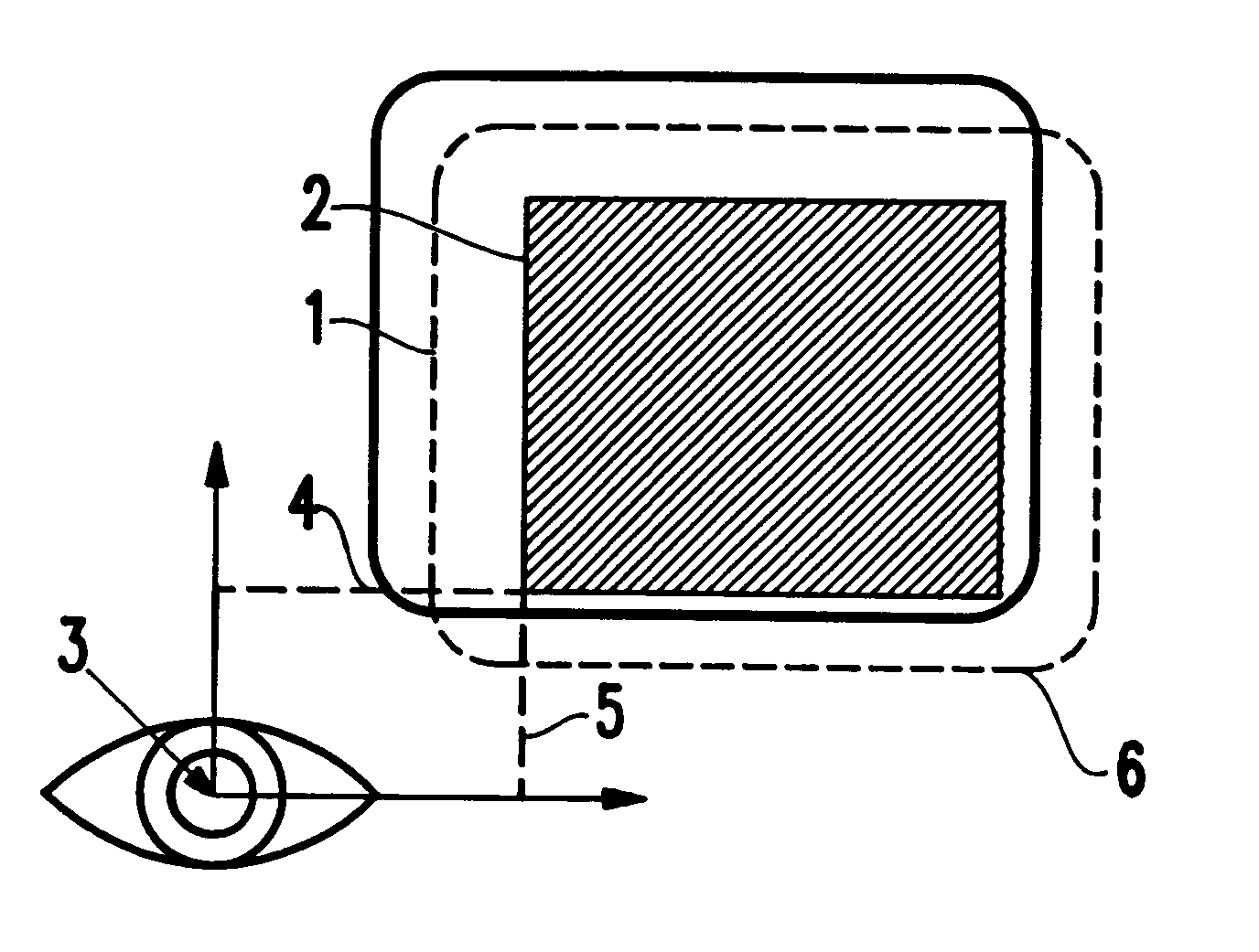
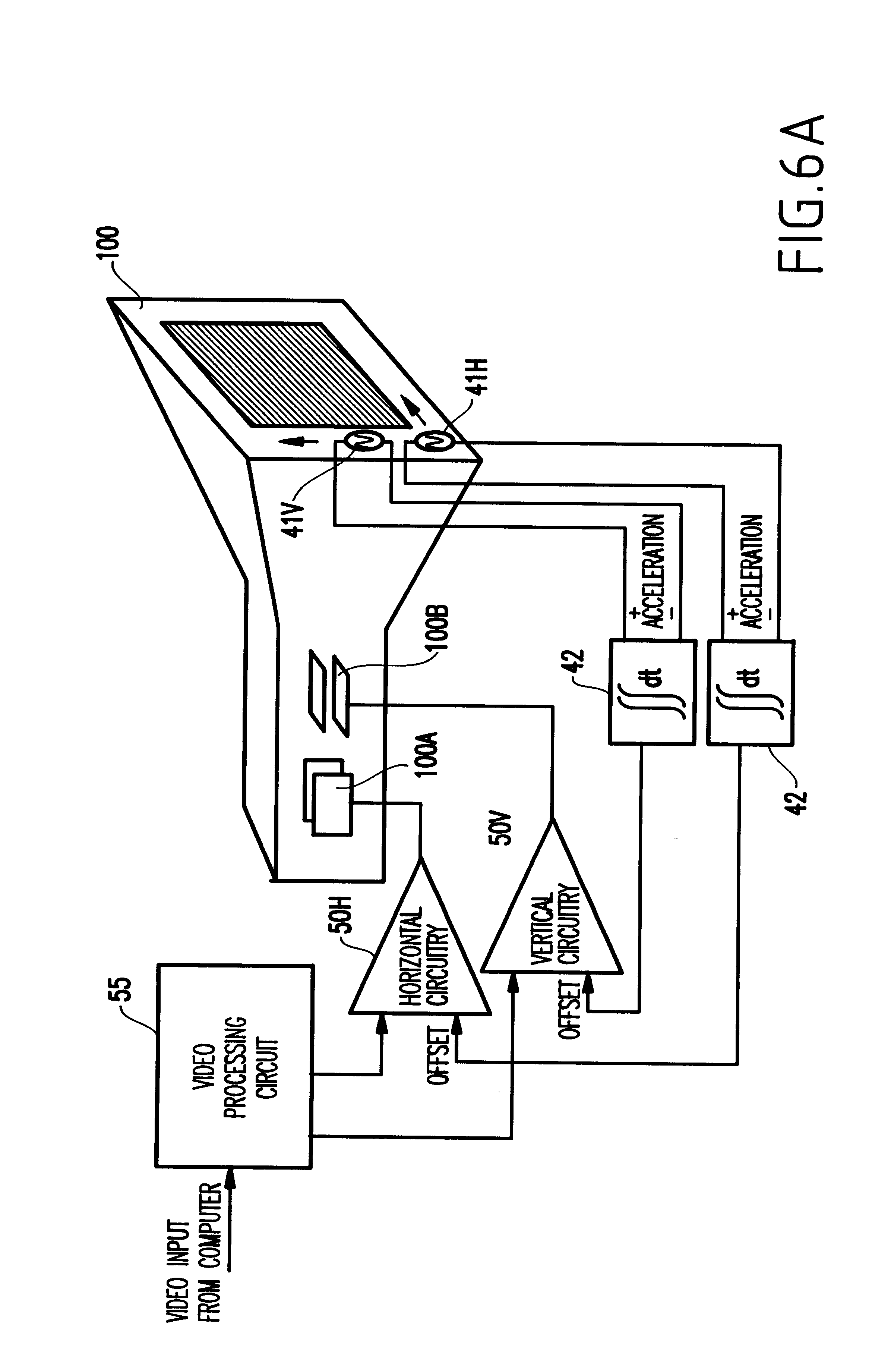
Generally, the present invention senses mechanical vibration and jitter induced on a display device displaying an electronic image thereon, and then shifts the displayed electronic image in the opposite direction to compensate for these jitters and to present a stable image to the observer's eye. As a result, the viewed image stays stationary (or substantially stationary) relative to the observer's gaze.

Turning now to the Figures, FIG. 1 illustrates a display 10 showing the function of the present invention. The display device 10 is typically formed by a liquid crystal display (LCD) or a thin-film transistor (TFT) panel, and has physical borders 1. The display can be a color display...


PUM


Abstract

An image stabilizing apparatus and method for a display device having a display screen, include a sensor for sensing a movement of the display device, and a movement compensation circuit, operatively coupled to the sensor, for compensating for the movement of the display device such that an image on the display screen of the display device remains substantially stationary in relation to an observer's gaze.

Description

1. Field of the InventionThe present invention generally relates to a method and apparatus for stabilization of an image, and more particularly to a video signal processing circuit and method used in performing vibration correction for an image on a display device.2. Description of the Related ArtIn recent years, electronic equipment including a display (e.g., such as a palmtop / laptop computer display, video games, televisions, display monitors, etc.) have become miniaturized and hence portable so that such equipment can be taken virtually anywhere and such equipment can be operated in virtually any environment including moving vehicles, boats, airplanes, etc.In a moving vehicle such as an automobile, a disadvantage of viewing, for example, a laptop computer's display, such as for the IBM Thinkpad.RTM., is the eye strain caused by vibrations and jitter of the vehicle. Further, the observer cannot easily follow the image during such vibration / jitter of the vehicle.Additionally, there...

Claims


Application Information

Patent Timeline
IPC IPC(8): G06F5/06G06F3/14G09G5/00G09G5/34G06F5/01H04N5/228G06F3/048
CPCG09G1/04G09G2320/0247G09G2320/0261
Inventor ABALI, BULENTFRANKE, HUBERTUSGIAMPAPA, MARK E.
Owner IBM CORP
Why Eureka
Try Eureka