Method for non-intrusively identifying a contained material utilizing uncollided nuclear transmission measurements
Inactive Publication Date: 2001-11-20
THE UNITED STATES AS REPRESENTED BY THE DEPARTMENT OF ENERGY
16 Cites 31 Cited by
AI-Extracted Technical Summary
Problems solved by technology
Unfortunately, defining the parameters of the attenuation equation, Equation (4), to enable calculation of .SIGMA..sub.C or .mu..sub.C is difficult, since the parameters are largely dependent on geometry.
In addition, where the target material, for example, is a chemical agent contained within a chemical munition made of a thick steel shell, the use of neutron transmission measu...
Abstract
An improved nuclear diagnostic method identifies a contained target material by measuring on-axis, mono-energetic uncollided particle radiation transmitted through a target material for two penetrating radiation beam energies, and applying specially developed algorithms to estimate a ratio of macroscopic neutron cross-sections for the uncollided particle radiation at the two energies, where the penetrating radiation is a neutron beam, or a ratio of linear attenuation coefficients for the uncollided particle radiation at the two energies, where the penetrating radiation is a gamma-ray beam. Alternatively, the measurements are used to derive a minimization formula based on the macroscopic neutron cross-sections for the uncollided particle radiation at the two neutron beam energies, or the linear attenuation coefficients for the uncollided particle radiation at the two gamma-ray beam energies. A candidate target material database, including known macroscopic neutron cross-sections or linear attenuation coefficients for target materials at the selected neutron or gamma-ray beam energies, is used to approximate the estimated ratio or to solve the minimization formula, such that the identity of the contained target material is discovered.
Application Domain
Material analysis by optical meansMachines/engines +5
Technology Topic
Attenuation coefficientUltrasound attenuation +7
Image
Examples
- Experimental program(8)
Example
In a first embodiment, neutron transmission measurements and a Two Energy Void/CA Algorithm are used to easily identify the chemical agent, based on the assumptions, principles, and chemical munition construction described in the Detailed Description of the Invention above. Two neutron beam energies are selected for conducting the uncollided neutron transmission measurements, in accordance with the apparatus illustrated in FIG. 1. Combinations of the energy pairs are selected, such that a ratio of known macroscopic neutron cross-sections for candidate chemical agents is unique for the chemical agent.
A first set of two neutron transmission measurements is conducted at first and second selected neutron beam energies, by transmitting a neutron beam through the chemical munition 20 along a selected transmission path at a selected cross-section 22, such that the neutron beam passes through the chemical agent containment area 34 containing a void space (air bubble). The uncollided neutron transmission responses at the two selected neutron beam energies are defined by the variables (I.sub.1, I.sub.2).sub.void, i.e., the count rate (I.sub.1).sub.void at the first neutron energy and the count rate (I.sub.2).sub.void at the second neutron energy. These measurements are described mathematically by Equations (5) and (6), normalized to the calibration constant K.
(I.sub.1).sub.VOID =K.sub.1 e.sup.-.SIGMA..sup..sub.S1 .sup.X.sup..sub.S e.sup.-.SIGMA..sup..sub.C1 .sup.x.sup..sub.C (5)
(I.sub.2).sub.VOID =K.sub.2 e.sup.-.SIGMA..sup..sub.S2 .sup.X.sup..sub.S e.sup.-.SIGMA..sup..sub.C2 .sup.x.sup..sub.C (6)
where
I.sub.1 is the count rate at the first neutron energy for the void space, in counts/second;
I.sub.2 is the count rate at the second neutron energy for the void space, in countg/second;
K.sub.1 is the radiation detector calibration constant for the first neutron energy, in counts/second, known;
K.sub.2 is the radiation detector calibration constant for the second neutron energy, in counts/second, known;
.SIGMA..sub.S1 is the macroscopic neutron cross-section through steel at the first neutron energy, either known or measured in cm.sup.-1 ;
.SIGMA..sub.S2 is the macroscopic neutron cross-section through steel at the second neutron energy, either known or measured in cm.sup.-1 ;
X.sub.S is the path length through the steel shell of the munition in centimeters, unknown;
X.sub.C is the path length through the chemical agent containment area (void space) contained within the munition in cm, unknown;
.SIGMA..sub.C1 is the macroscopic neutron cross-section through the chemical agent containment area (void space) at the first neutron energy, unknown; and
.SIGMA..sub.C2 is the macroscopic neutron cross-section through the chemical agent containment area (void space) at the second neutron energy, unknown.
Importantly, since it is assumed that the uncollided neutron transmission through the void space alone results in a neutron transmission measurement approximately equal to 1.0, the uncollided neutron transmission responses (I.sub.1, I.sub.2).sub.void describe the probability of zero neutron-nucleus interactions occurring along the path length of the steel shell only, at the two selected neutron energies. This is more clearly described by rewriting Equations (5) and (6) as Equations (7) and (8), respectively. ##EQU5##
Next, the chemical munition 20 is re-oriented, preferably by inverting the chemical munition 20, such that the unidentified chemical agent now occupies the volume within the chemical agent containment area 34 of the chemical munition 20 at the selected cross-section 22, previously occupied by the void space. In this way, the neutron transmission measurements performed for the chemical agent have the identical geometry, or path length X.sub.C, as the neutron transmission measurements performed for the void space.
A second set of two neutron transmission measurements is conducted for the chemical agent (CA) at the same first and second neutron beam energies as the neutron transmission measurements conducted previously for the void space, by transmitting a neutron beam through the chemical munition 20 along the same selected transmission path, such that the neutron beam passes through the chemical agent containment area 34 containing the chemical agent. The resulting count rate measurements (I.sub.1, I.sub.2).sub.CA are detected at the on-axis neutron detector. The parameters of the neutron transmission measurements for the void spate (I.sub.1, I.sub.2).sub.void and chemical agent (I.sub.1, I.sub.2).sub.CA measurements are constant, except for the orientation of the chemical munition, a modification that does not affect any path length parameters.
The Two Energy Void/CA Algorithm is applied to formulate a first ratio of the void space uncollided neutron transmission measurement at the first energy to the chemical agent uncollided neutron transmission measurement at the first energy, and a second ratio of the void space uncollided neutron transmission measurement at the second energy to the chemical agent uncollided neutron transmission measurement at the second energy, such that the contribution of the uncollided neutron transmission through the steel shell only is effectively eliminated from both ratios, assuming the uncollided neutron transmission through the void space is nearly 1.0 counts/second. The next step of the algorithm involves formulating a third ratio of the first ratio to the second ratio, or a ratio of the macroscopic neutron cross-section ratio for the uncollided neutron transmission for the chemical agent only at the first energy to the macroscopic neutron cross-section for the uncollided neutron transmission for the chemical agent only at the second energy. These steps of the algorithm are applied as follows.
The first ratio and second ratios are described by Equations (9) and (10), as the natural logs of the ratios of the void space uncollided neutron transmission measurements (I.sub.1, I.sub.2).sub.void to the chemical agent uncollided neutron transmission measurements (I.sub.1, I.sub.2).sub.CA at the first and second neutron energies. ##EQU6##
Equations (9) and (10) individually represent the product of the macroscopic neutron cross-section at the selected energy and the path length of the neutron transmission through the chemical agent containment area.
Equation (11) describes the third ratio, the ratio of Equation (9) to Equation (10), representing the final result--the estimated ratio of the chemical agent macroscopic neutron cross-sections at the first and second energies. ##EQU7##
Since macroscopic neutron cross-sections at selected energies are unique to chemical agents, a ratio of macroscopic neutron cross-sections at two selected energies is similarly useful for identifying the contained chemical agent. Known macroscopic neutron cross-section values for candidate chemical agents at the selected first and second neutron energies are used to calculate the ratio described by Equation (11), and the target chemical agent contained within the chemical munition 20 is identified by determining which candidate chemical agent produces the closest match. Preferably, a candidate chemical agent database and other computerized systems are configured for the easy selection of candidate chemical agents, calculation of the required ratios, comparison of calculated muid measured ratios, and identification of the chemical agent.
Table III below lists examples of macroscopic neutron cross-section values for selected chemical agents at various neutron energies for a 155 mm chemical ordnance obtained from radiation transport calculations executed in accordance with the Monte Carlon-Particle transport code (MCNP) for simulating the transport of neutrons.
Example
Embodiment 1 Adapted to Gamma-ray Measurement Transmissions
The first embodiment of 
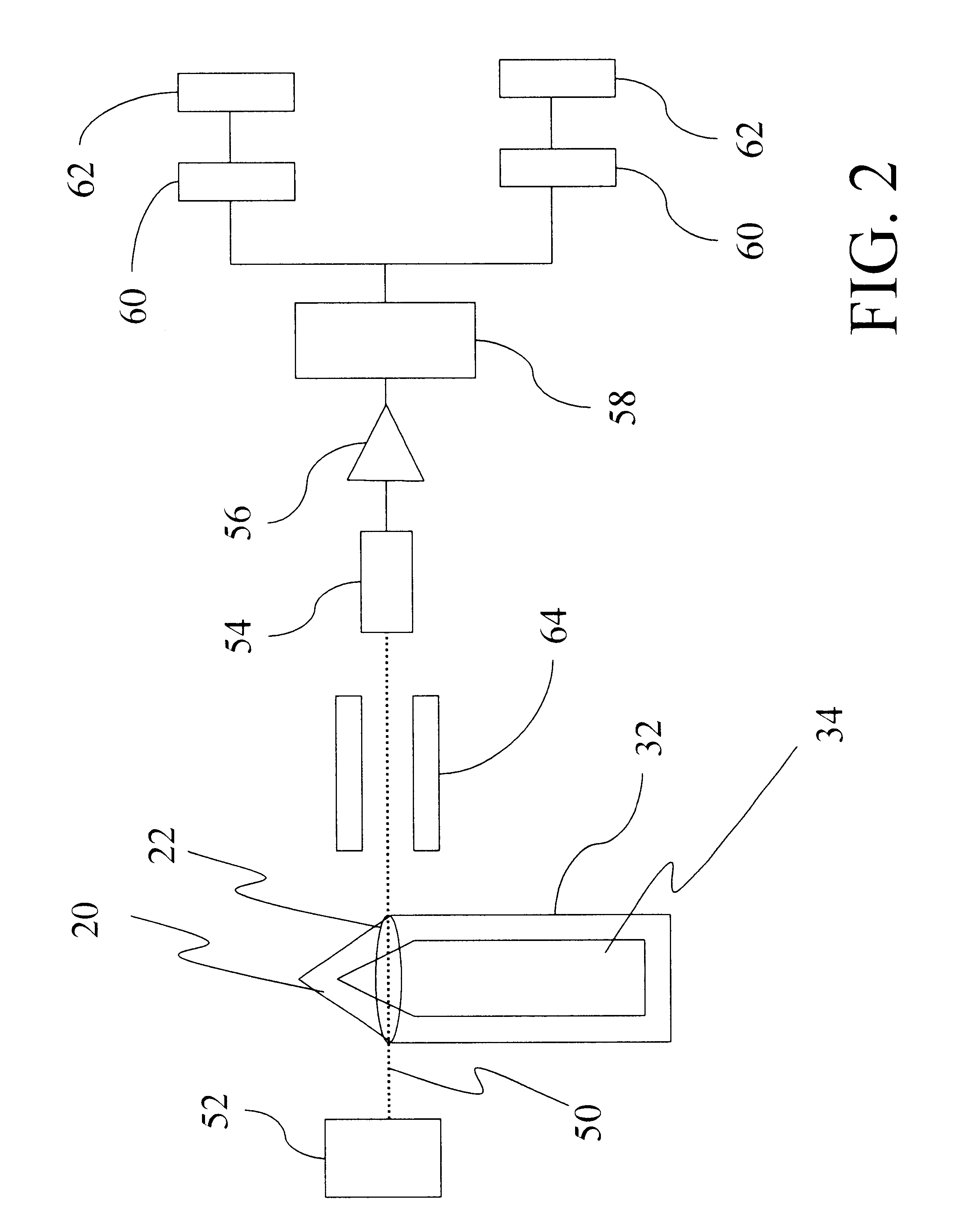
the present method is also valid for non-interacting photon measurements, wherein a gamma beam is used to interrogate the chemical munition 20, rather than neutron transmissions. FIG. 2 illustrates the apparatus appropriate for practicing the present embodiment, which is based on the assumptions, principles, and chemical munition construction described in the Detailed Description of the Invention above. Two gamma-ray beam energies are selected for conducting the non-interacting photon transmission measurements.
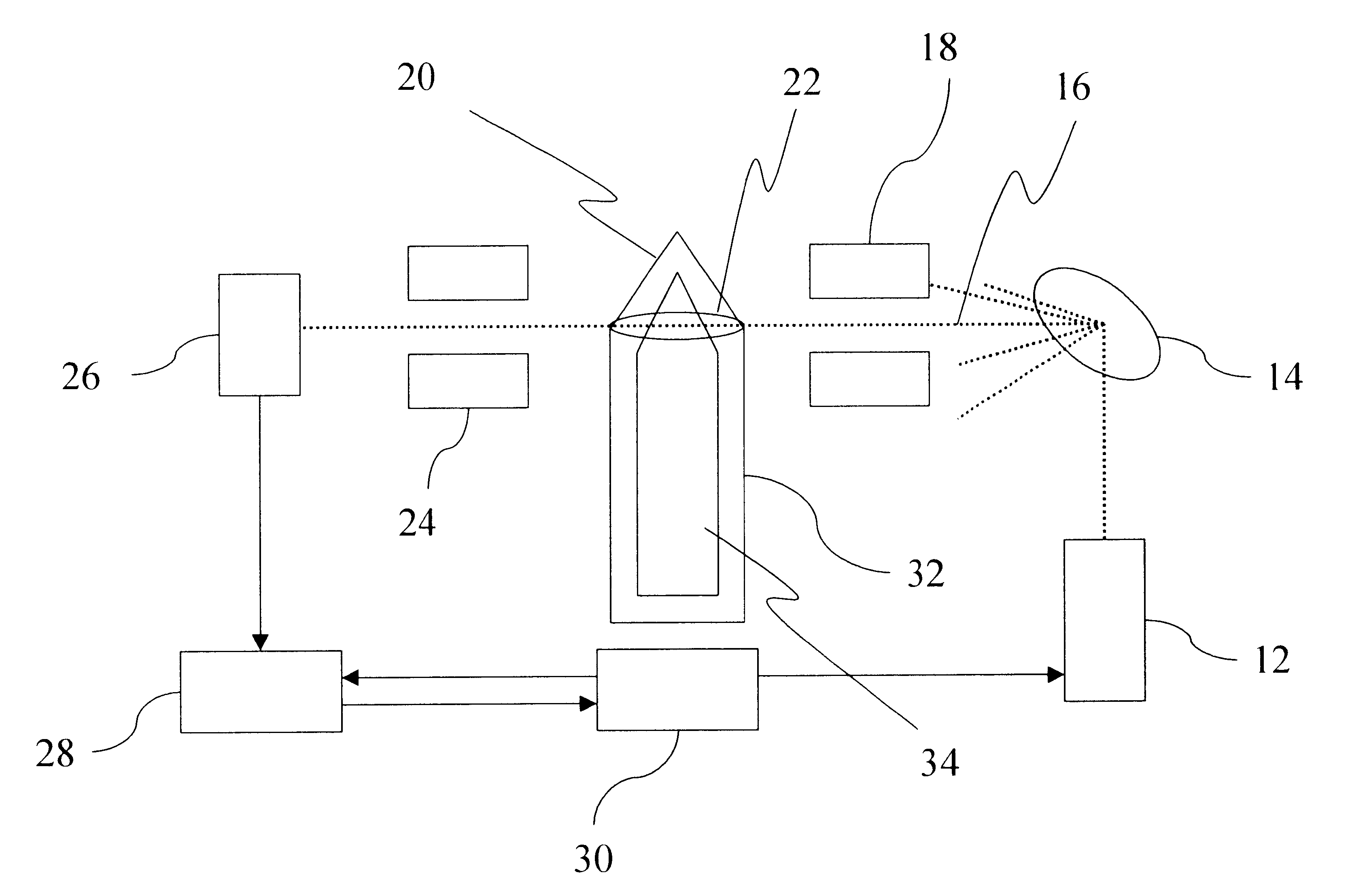
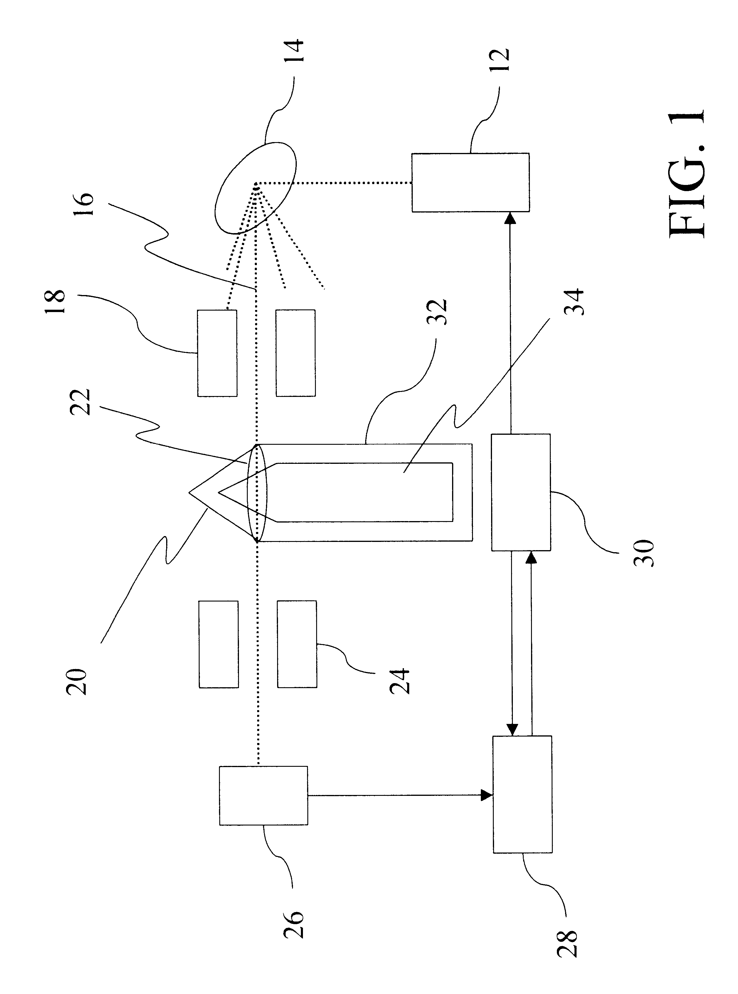
A first set of two gamma-ray transmission measurements is conducted at the first and second selected gamma-ray beam energies, by passing a gamma-ray beam through the chemical agent 20 along a selected transmission path at a selected cross-section 22, such that the gamma-ray beam passes through the chemical agent containment area 34 containing a void space, and by detecting the corresponding non-interacting photon transmission responses. Next, the chemical munition 20 is re-oriented, such that the chemical agent now occupies the volume within the chemical agent containment area 34 previously occupied by the void space. A second set of two gamma-ray transmission measurements are conducted along selected transmission path through the chemical munition 20, including transmission through the chemical agent, at the same first and second gamma beam energies.
The gamma linear attenuation coefficient (.mu..sub.i) for the selected first and second energies, e.sub.i, comprises the ratio for identifying the chemical agent, rather than the macroscopic neutron cross-sections described above. The gamma linear attenuation coefficient is a function of the chemical agent molecular structure and the gamma photon energy. For a single photon energy, the gamma linear attenuation coefficient at a selected energy is related to the count rate through the liquid chemical agent and the count rate through the gas (void space) by Equation (12). ##EQU8##
where N.sub.g is the count rate through the gas, or void space;
N.sub.f is the count rate through the liquid chemical agent;
.mu..sub.f is the gamma linear attenuation coefficient for the gamma at the selected energy; and
x is the path length through the liquid/gas space.
Assuming two different photon energy gamma rays are detectable, the ratio Q(e.sub.1, e.sub.2) of the linear attenuation coefficients at the selected first and second energies e.sub.1, e.sub.2 identifies the chemical agent, as expressed in Equation (13). ##EQU9##
Known gamma-ray linear attenuation coefficients for candidate chemical agents at the selected first and second gamma-ray energies are used to calculate the ratio described by Equation (13), and the target chemical agent contained within the chemical munition 20 is identified by determining which candidate chemical agent produces the closest match.
Advantageously, this embodiment relies on non-interaction of the gamma beam over a measured path length that is ultimately eliminated from the identification ratio, such that the existence of localized abnormalities, e.g., surface corrosion, do not affect the accuracy of the measurement.
Example
In a second embodiment, a Two Energy CA Algorithm is applied, such that neutron transmission measurements through a void space and rotation of the chemical agent are not required. The Two Energy CA Algorithm utilizes the total path length relationship to eliminate unknown variables to derive a minimization formula having a solution that identifies the chemical agent. The present embodiment is based on the assumptions, principles, and chemical munition construction described in the Detailed Description of the Invention above. First and second neutron beam energies are selected for conducting the uncollided neutron transmission measurements.
Two neutron transmission measurements are conducted at the first and second neutron energies, by passing a neutron beam through a selected transmission path at a selected cross-section 22 of the chemical munition 20, such that the neutron beam passes through the steel shell 32 and the chemical agent containment area 34 containing the chemical agent (CA). The resulting uncollided neutron measurements are described by Equations (14) and (15). ##EQU10##
where
I.sub.1 is the count rate at the first neutron energy for the chemical munition, in counts/second;
I.sub.2 is the count rate at the second neutron energy for the chemical munition, in counts/second;
K.sub.1 is the radiation detector calibration constant for the first neutron energy, in counts/second, known;
K.sub.2 is the radiation detector calibration constant for the second neutron energy, in counts/second, known;
.SIGMA..sub.S1 is the macroscopic neutron cross-section through steel at the first neutron energy, either known or measured in cm.sup.-1 ;
.SIGMA..sub.S2 is the macroscopic neutron cross-section through steel at the second neutron energy, either known or measured in cm.sup.-1 ;
.SIGMA..sub.C1 is the macroscopic neutron cross-section through the chemical agent within the containment area at the first neutron energy, unknown;
.SIGMA..sub.C2 is the macroscopic neutron cross-section through the chemical agent within the containment area at the second neutron energy, unknown;
X.sub.S is the path length through the steel shell of the munition in centimeters, unknown; and
X.sub.C is the path length through the chemical agent within the containment area in cm, unknown,
Variables C.sub.1 and C.sub.2 are next defined in terms of the natural log of Equations (14) and (15). ##EQU11##
Given the total path length relationship D=X.sub.S +X.sub.C, Equations (14), (15), (16), and (17) are combined in Equation (18). ##EQU12##
The solution for Equation (18) is expressed by Equations (19) and (20). ##EQU13##
Substituting the terms of Equations (19) and (20) into the total path length equation D=X.sub.S +X.sub.C results in Equation (21). ##EQU14##
Equation (21) is rewritten in a simplified form as Equation (22).
.SIGMA..sub.C2 (C.sub.1 -D.SIGMA..sub.S1)-.SIGMA..sub.C1 (C.sub.2 -D.SIGMA..sub.S2)=.SIGMA..sub.S2 C.sub.1 -.SIGMA..sub.S1 C.sub.2 (22)
All variables in Equation (22) are known, with the exception of .SIGMA..sub.C1, .SIGMA..sub.C2, the macroscopic neutron cross-section measurements through the chemical agent at the first and second neutron energies. Known pairs of macroscopic neutron cross-sections for a candidate chemical agents at the two selected neutron energies are used to solve Equation (22). Preferably, the related minimization formula, Equation (23), easily determines the optimum candidate, by successively evaluating candidate chemical agents and their corresponding macroscopic neutron cross-sections, .SIGMA..sub.C1, .SIGMA..sub.C2, to determine the chemical agent exhibiting the closest fit.
Err=.SIGMA..sub.C2 (C.sub.1 -D.SIGMA..sub.S1)-.SIGMA..sub.C1 (C.sub.2 -D.SIGMA..sub.S2)-.SIGMA..sub.S2 C.sub.1 +.SIGMA..sub.S1 C.sub.2 (23)
A database of candidate chemical agents and computerized systems may easily be configured to solve Equation (23).
For first and second neutron energies of 0.0275 Mev and 1.372 MeV, Table IV below provides error information for simulations for identifying the chemical agents GA, GB, GD, and VX, in accordance with Equations (22) and (23).
PUM


Description & Claims & Application Information
We can also present the details of the Description, Claims and Application information to help users get a comprehensive understanding of the technical details of the patent, such as background art, summary of invention, brief description of drawings, description of embodiments, and other original content. On the other hand, users can also determine the specific scope of protection of the technology through the list of claims; as well as understand the changes in the life cycle of the technology with the presentation of the patent timeline. Login to view more.