Eureka AIR delivers breakthrough ideas for toughest innovation challenges, trusted by R&D personnel around the world.

Buckling pin actuated, pilot operated pressure relief valve

Inactive Publication Date: 2001-12-04
BS&B SAFETY SYST LTD
View PDF38 Cites 37 Cited by
  • Summary
  • Abstract
  • Description
  • Claims
  • Application Information

AI Technical Summary

Problems solved by technology

This principle does not apply if the bucking pin material is subject to an intervening mode of failure due to eccentric loading, material defects or yield stress limitations.
Consequently, the conventional use of buckling pins limits the relief capacity of the valve, requiring either redundant valves or excessively large valves in order to obtain the desired flow capacity.
With existing buckling pin design large valves or high pressure valves require a very long or large buckling pins, often resulting in a buckling pin that is of an awkward length or size for reliable prediction of buckling pin failure.
Unfavorable slenderness ratios and intervening failure modes related to material yield stress, material defects or eccentric loading causes problems with buckling pin design and selection.
Longer collapse displacements required by large valves require longer, larger and more expensive buckling pins.
Reliability and accuracy of predicted buckling pin failure loads are lost due to unfavorable slenderness ratios and the increasing intervention of other pin failure modes.
Intervening failures related to material defects, material yield stress limitations and manufacturing irregularities may determine the ultimate load of the buckling pin.
Inaccuracies and poor reliability result from wear or friction losses introduced by movable mechanical joints, all of which are magnified by the scaled mechanical advantage gained in the linkage, and result in an overall loss of valve accuracy and reliability.
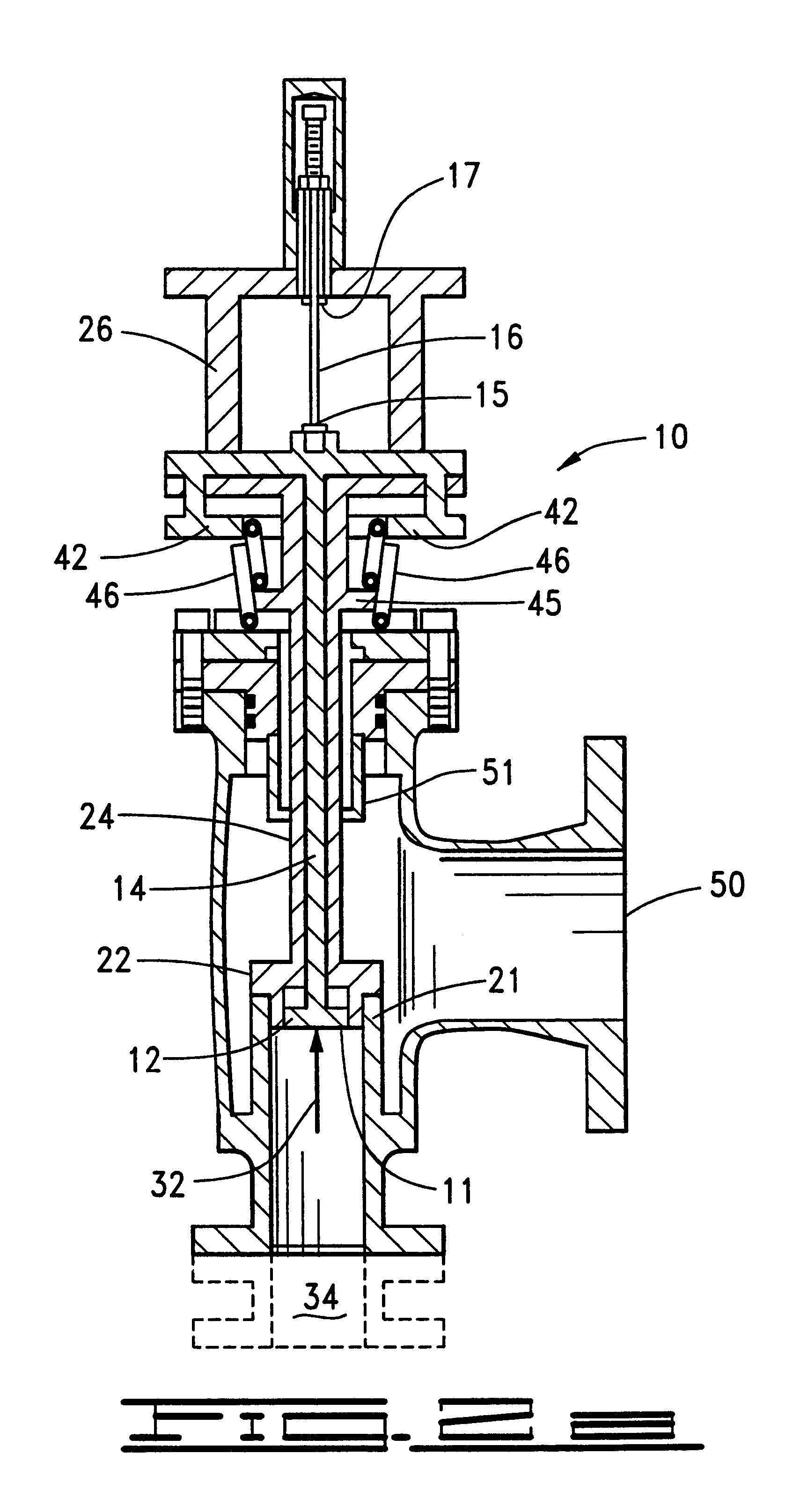
When the force exerted on the face of the sensing piston exceeds the compressive load bearing capacity of the buckling pin, buckling mode failure of the pin occurs, with simultaneous release and displacement of the latch arms relative to the latch mechanism.
The flow capacity achieved by this valve design far exceeds the flow capacity that could be obtained by the limited displacement of the piston provided by the collapse of the buckling pin.
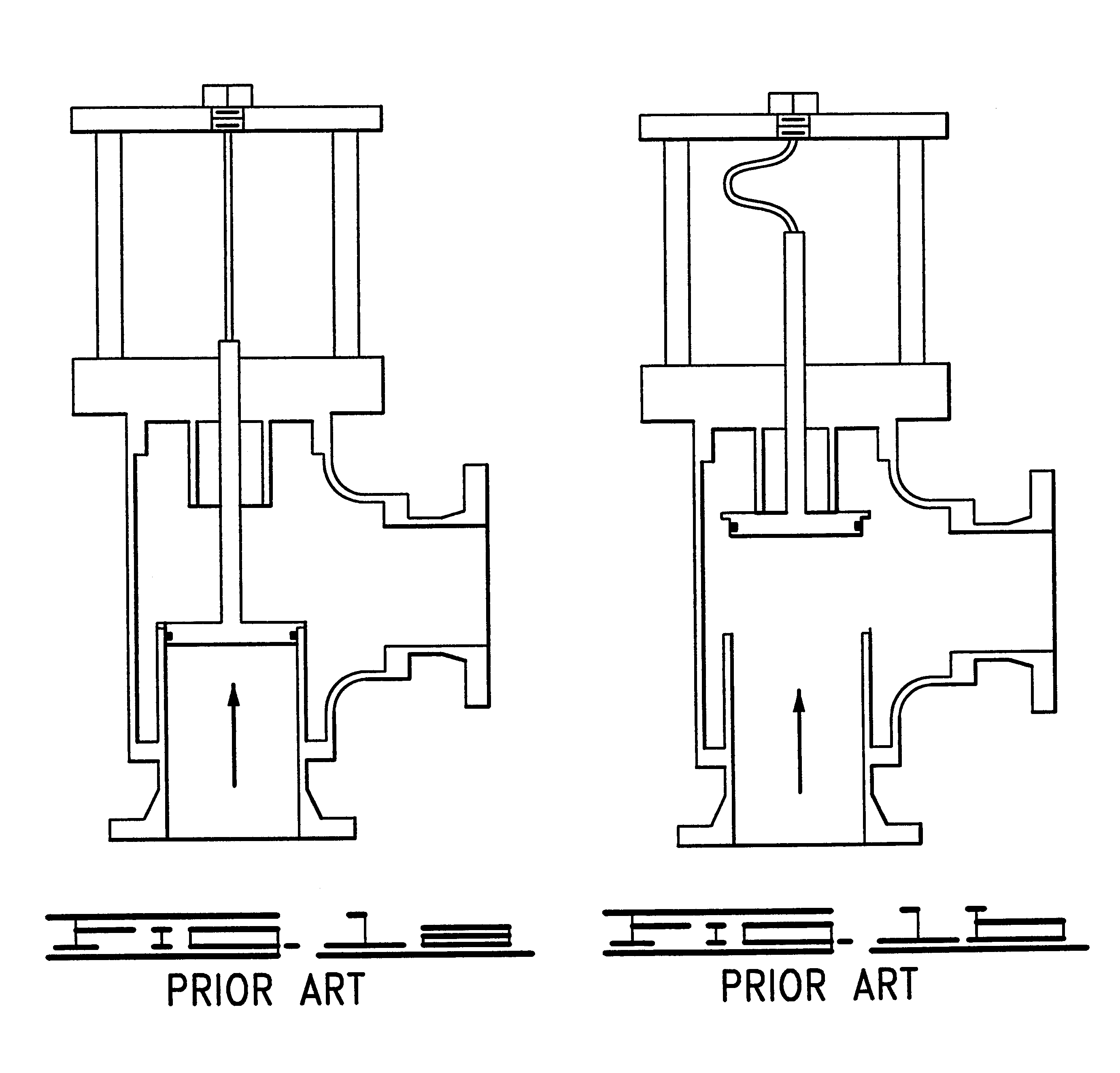
These systems tend to be somewhat unreliable due to inaccurate set pressures and may become inoperative should the pilot valve or pilot piping become clogged due to the pilot's or the piping's relatively small size.
Such pilot systems may become cost prohibitive in the larger sizes.
Using a rupture pin valve by itself may result in control problems such as "slamming" open.
These systems also may require large, expensive replacement buckling pins and may result in very large valves and relief systems.
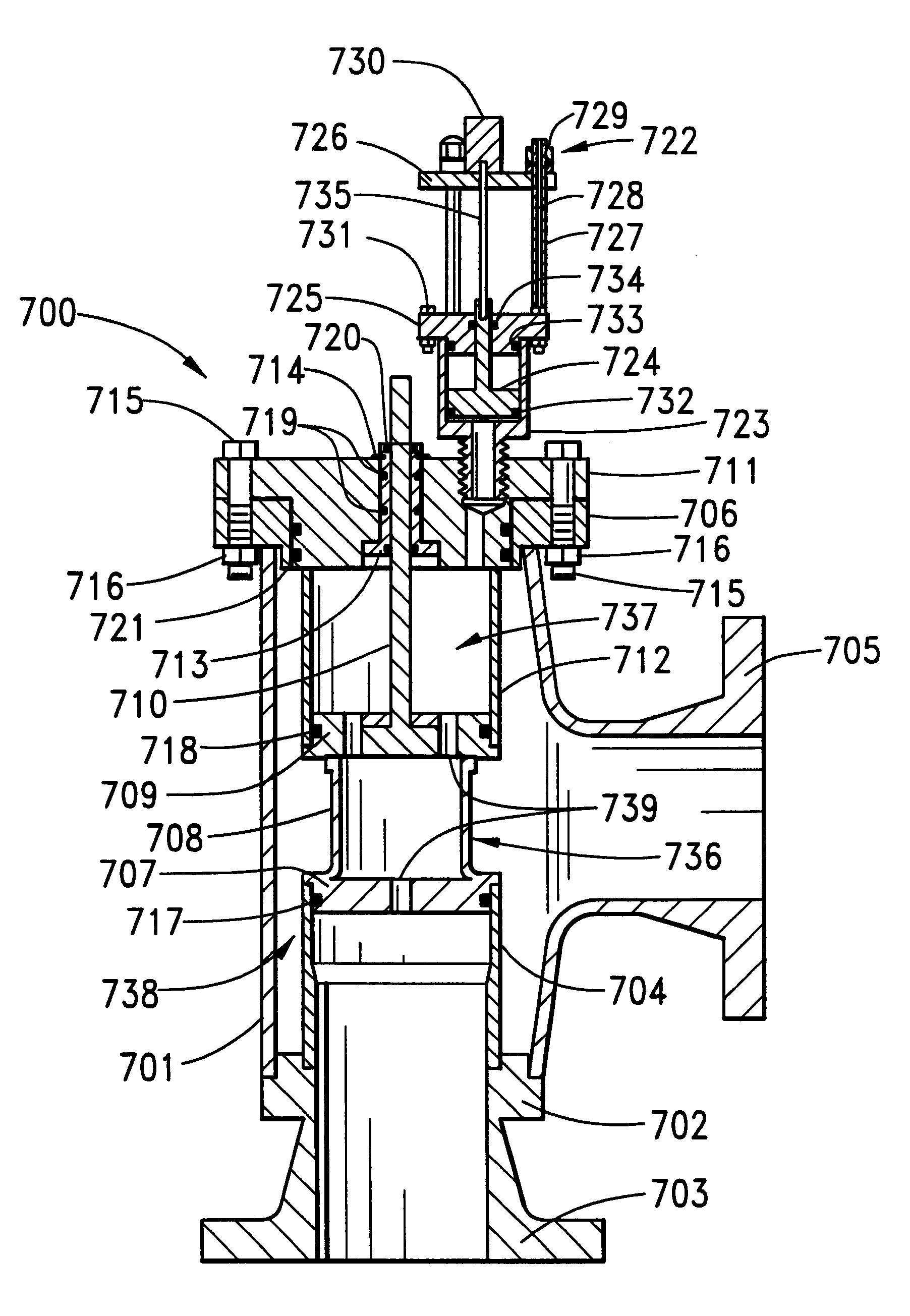
The balance chamber assembly includes at least two pistons of different areas so that the failure of the buckling pin results in differential forces acting on the pistons causing them to open the flow from the inlet to the outlet.
The balance chamber assembly includes at least two pistons of different areas so that the failure of the buckling pin results in differential forces acting on the pistons causing them to open the flow from inlet to outlet.
The forces are transmitted to a buckling pin in the pilot valve to cause it to fail at a predetermined pressure, that is, the buckling pin is caused to fail when the pressure exceeds a predetermined pressure.
The failure of the buckling pin causes the displacement of the pistons to permit the flow of fluid from inlet to outlet.

Method used


Image

  • Buckling pin actuated, pilot operated pressure relief valve
  • Buckling pin actuated, pilot operated pressure relief valve
  • Buckling pin actuated, pilot operated pressure relief valve

Examples


Embodiment Construction

For a further understanding of the nature, function, and objects of the present invention, reference should now be made to the following detailed description taken in conjunction with the accompanying drawings. Detailed descriptions of the preferred embodiments are provided herein, as well as, the best mode of carrying out and employing the present invention. It is to be understood, however, that the present invention may be embodied in various forms. Therefore, specific details disclosed herein are not to be interpreted as limiting, but rather as a basis for the claims and as a representative basis for teaching one skilled in the art to employ the present invention in virtually any appropriately detailed system, structure, or manner. The practice of the present invention is illustrated by the following examples, which are deemed illustrative of both the process taught by the present invention and of the product and article of manufacture yielded in accordance with the present inven...


PUM


Abstract

The present invention provides a method, apparatus and system for using sacrificial buckling pin technology for a reliable actuated safety relief valve and for a pilot valve system. The buckling pin fails at a predicted, predetermined system pressure through transfer of force exerted by the system pressure on a sensing piston or diaphragm to the buckling pin. The buckling pin failure triggers the release of a latch mechanism that releases the actuator assembly to slide away from the valve seat to initiate relief flow. The use of the buckling pin as a trigger for release of a latch provides for valves with high flow rates without the use of large, unmanageable buckling pins. The use of a buckling pin valve as a pilot valve to control a single or multiple relief valves operating together as a pressure relief system is preferred as particularly advantageous.

Description

1. Field of the InventionThe present invention relates to actuated safety relief valves. More specifically, the present invention relates to actuated relief valves that use a sacrificial buckling pin as a trigger for an actuator and to pilot valve safety relief system.2. Background of the Invention and Related ArtThe use of sacrificial buckling pins is widely known in the valve industry. Through the selection and use of appropriate materials, buckling pins can be designed to fail with a high degree of reliability and accuracy upon the application of a predetermined axial compressive force. The maximum compressive load for a buckling pin is dependent on its slenderness, which is a function of the pin length and the diameter of its cross-section. For compressive axial failure, the ultimate compressive capacity of the pin is easily calculated using Euler's law relating the critical force to the modulus of elasticity of the material, the minimum moment of inertia of the cross section an...

Claims


Application Information

Patent Timeline
IPC IPC(8): F16K17/04F16K17/00F16K17/40
CPCF16K17/042F16K17/406Y10T137/1782Y10T137/7764Y10T137/7769Y10T137/7832
Inventor SCANTLIN, GARY W.
Owner BS&B SAFETY SYST LTD
Why Eureka
Eureka Blog
Learn More