Capacitively-tuned broadband antenna structure

a broadband antenna and capacitive tuning technology, applied in the direction of radiating element structural forms, polarised antenna unit combinations, resonant antennas, etc., can solve the problems of high-speed manufacturing and assembly techniques of wireless communication devices, large external assembly of whip antennas, and inability to meet the requirements of high-speed manufacturing and assembly techniques

Inactive Publication Date: 2001-12-04
TYCO ELECTRONICS LOGISTICS AG (CH)
View PDF16 Cites 58 Cited by
  • Summary
  • Abstract
  • Description
  • Claims
  • Application Information

AI Technical Summary

Problems solved by technology

Additionally, the external assembly of a whip antenna can be relatively massive (weighing 8-9 grams) and may be subject to damage during use.
High-speed manufacturing and assembly techniques of wireless communication devices are typically not practicable with whip antennas, as such antennas typically require manual as

Method used


Image

  • Capacitively-tuned broadband antenna structure
  • Capacitively-tuned broadband antenna structure
  • Capacitively-tuned broadband antenna structure

Examples


Embodiment Construction

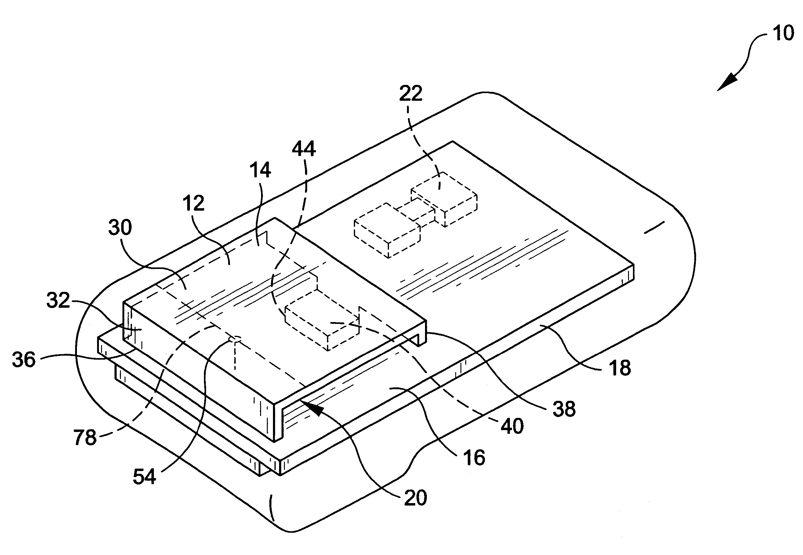
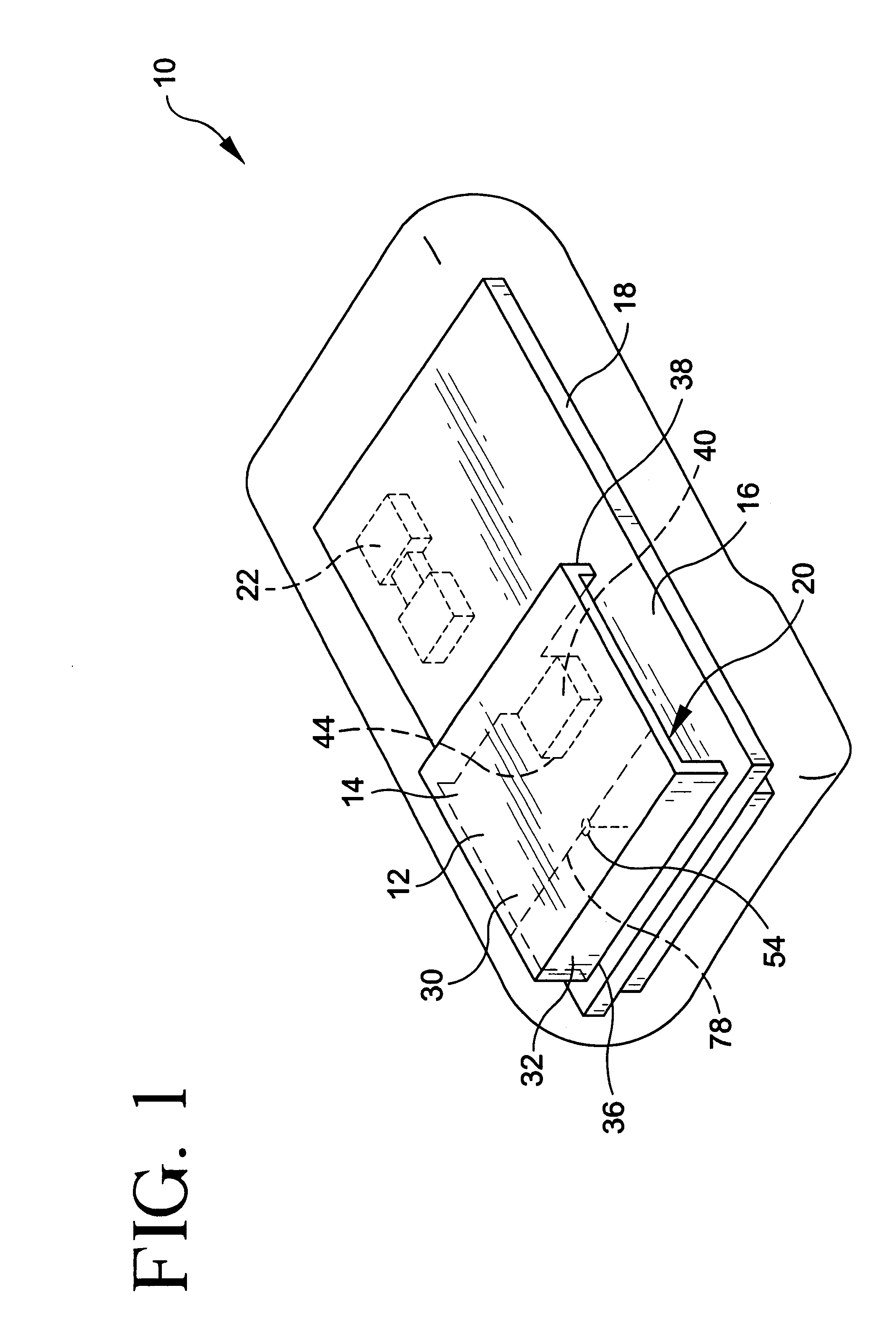
FIG. 1. is a perspective view showing the internal structure of a wireless communication device 10, such as a cellular phone, including the antenna assembly 12 according to the present invention. It should be appreciated that the antenna assembly 12 of this invention is suitable for use with other wireless communication devices 10 such as hand-held radios, and other portable wireless communication devices that emit electromagnetic radiation.

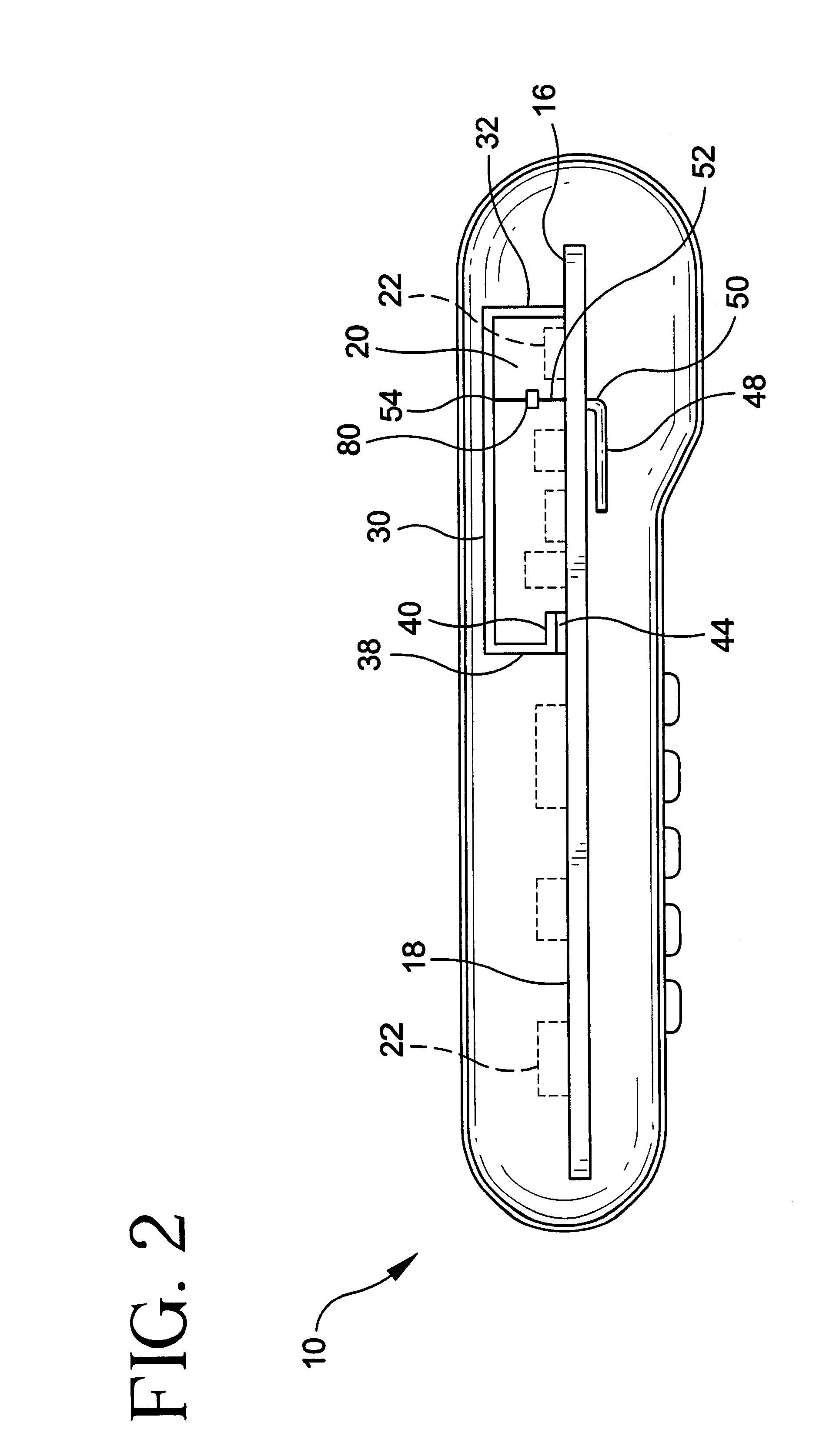
FIGS. 1 and 2 show an antenna assembly 12 embodying the present invention for operation over the 824-894 MHz frequency range. Alternative frequency range operations would be appreciated by those skilled in the arts. Performance characteristics may be affected by changes of the physical sizes and dimensions of the antenna assembly 12 component geometry. Such changes, alterations, or modifications may be made by those skilled in the relevant arts, though not departing from the scope of the invention disclosed herein.

The antenna assembly 12 includes...


PUM


Abstract

An antenna assembly for a wireless communication device for receiving and transmitting a communication signal is disclosed. The wireless communication device having a ground plane element and a feedline conductor, said antenna assembly including a configured radiating conductor element having a pair of opposed ends disposed proximate the ground plane element and an intermediate extending portion disposed away from the ground plane element to define an interior region, said first end operatively coupled to the ground plane element, said second end capacitively coupled to the ground plane element, and said intermediate extending portion operatively coupled to the feedline conductor at a feedpoint between the first end and the second end.

Description

This invention relates generally to a compact antenna structure, and in particular to an antenna structure which is suitably utilized with a wireless communication device.BACKGROUND OF IN THE INVENTIONMany wireless transceivers, and hand-held cell phones in particular, currently use external whip antennas that radiate nominally omnidirectionally. Little or no reduction is provided in transmitted RF energy that is directed toward the user's head. As a result, typical specific absorption rate (SAR) values of 2.7 mw / g at 0.5 watts input are realized. Additionally, the external assembly of a whip antenna can be relatively massive (weighing 8-9 grams) and may be subject to damage during use. The gain performance characteristic of the whip antenna is typically in the range -5 to +1.5 dBi. High-speed manufacturing and assembly techniques of wireless communication devices are typically not practicable with whip antennas, as such antennas typically require manual assembly and installation.Al...

Claims


Application Information

Patent Timeline
IPC IPC(8): H01Q1/24H01Q23/00H01Q9/04H01Q21/24H01Q1/38H01Q13/08H01Q21/30
CPCH01Q1/243H01Q9/0421H01Q9/0442H01Q9/0457H01Q23/00H01Q1/24
Inventor JOHNSON, GREGHILL, ROBERTKEILEN, DON
Owner TYCO ELECTRONICS LOGISTICS AG (CH)
Why Eureka
Try Eureka