Brake operating device with modulator

Inactive Publication Date: 2001-12-11
SHIMANO INC
View PDF14 Cites 29 Cited by
  • Summary
  • Abstract
  • Description
  • Claims
  • Application Information

AI Technical Summary

Problems solved by technology

However, this increased braking power may be difficult for the inexperienced rider to control.
Specifically, a bicycle brake with a very large braking power can possibly cause the bicycle wheel to lock up.
This may cause the bicycle to skid for the inexperienced rider.
This arrangement does not allow the rider to view the operation of the modulator.
W

Method used


Image

  • Brake operating device with modulator
  • Brake operating device with modulator
  • Brake operating device with modulator

Examples


third embodiment

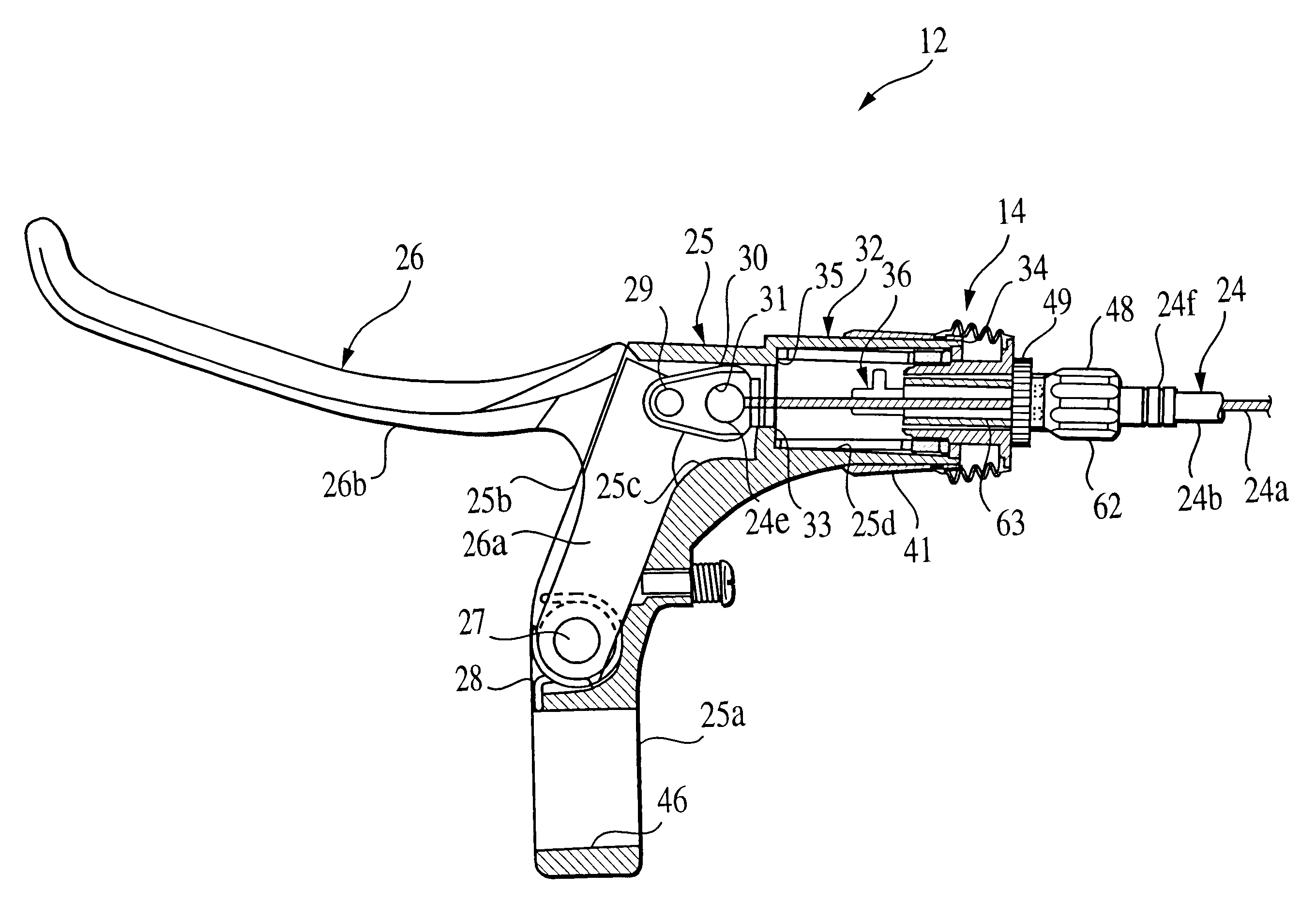
Referring now to FIG. 11, the braking power modulator 14" of the brake operating device 12 has been modified in accordance with a third embodiment of the present invention. Specifically, the brake operating device 12 as illustrated in FIG. 11 is identical to the first embodiment, discussed above, except that a modified modulating bolt or member 47" is used in the third embodiment of the present invention. Thus, only the differences between the first and third embodiments will be discussed herein. Moreover, the reference numerals of the first embodiment will be used to indicate the parts of this third embodiment that are the same parts in the first embodiment.

In this embodiment, modulating bolt or member 47" has a smooth cable receiving bore 54" (no threads) similar to the second embodiment, except that a longitudinally extending protrusion 54a is formed on cable receiving bore 54". This protrusion 54a is adapted to overridably engage the longitudinally extending slot 66 of cable ten...

fourth embodiment

Referring now to FIG. 12, the braking power modulator 14'" of the brake operating device 12 has been modified in accordance with a fourth embodiment of the present invention. Specifically, the brake operating device 12 as illustrated in FIG. 12 is identical to the first embodiment, discussed above, except that in this embodiment the adjusting member 43, the preload nut 44, the sealing member 46 and the modulating member 47 have been replaced with a modified adjusting nut or member 43'" and a modified modulating bolt or member 47'". Thus, only the differences between the first and fourth embodiments will be discussed herein. Moreover, the reference numerals of the first embodiment will be used ti indicate the parts of this fourth embodiment that are the same parts in the first embodiment.

Basically, modulating member 47'" has been designed so that a preload flange 44'" is integrally formed therewith. In other words, the preload nut 44 of the first embodiment has been made to be integr...


PUM


Abstract

A braking power modulator is coupled to the brake lever of a brake operating device for easy adjustment and viewing. The braking power modulator is preferably adjustable to provide different braking powers for different riders or different road conditions. The braking power modulator basically includes a mounting member, a brake lever, a biasing member, a modulating member and an adjusting member. The mounting member is adapted to be coupled to a handlebar of a bicycle, and has a cable passageway with a first abutment and a second abutment. The brake lever is pivotally coupled to the mounting member, and has a cable attachment portion. The biasing member is disposed in the cable passageway, and has first and second portions with the first portion of the biasing member being operatively coupled to the first abutment. The modulating member with the adjusting member coupled thereto is movably arranged within the cable passageway and operatively biased against the second abutment by the second portion of the biasing member. The adjusting member is movably arranged along the modulating member and biased toward the second abutment of the mounting member. A cable tensioning member is adjustably coupled to the modulating member. The biasing member is disposed in the tubular portion of the brake lever under a preloaded state with a pre-set compression force. The adjusting member engages the biasing member to change the pre-set compression force of the biasing member without changing the predetermined modulator stroke of the second blocking portion.

Description

1. Field of the InventionThis invention generally relates to a braking power modulator for a bicycle brake device. More specifically, the present invention relates to a brake operating device with a braking power modulator coupled thereto. Preferably, the present invention relates to an adjustable braking power modulator that provides different braking powers to meet the needs of different riders or different road conditions.2. Background InformationBicycling is increasingly becoming a more popular form of recreation as well as a means of transportation. Moreover, bicycling has become a very popular competitive sport for both amateurs and professionals. Whether the bicycle is used for recreation, transportation or competition, the bicycle industry is constantly improving the various components of the bicycle. One component that has been extensively redesigned is the bicycle brake and its brake operating device. The bicycle brake has been redesigned over the years to provide the ride...

Claims


Application Information

Patent Timeline
IPC IPC(8): B62L3/00B62L3/02B60T11/04
CPCB62L3/00B62L3/02B60T11/046B62L1/14Y10T74/2045Y10T74/20438Y10T74/20287Y10T74/20462
Inventor TAKIZAWA, SHINICHI
Owner SHIMANO INC
Why Eureka
Try Eureka