Insulating cover

a technology of insulating cover and cover plate, which is applied in the field of insulating cover, can solve the problems of reducing the overall insulating effect of the cover plate,

Inactive Publication Date: 2001-12-11
COMBI THERM
View PDF1 Cites 11 Cited by
  • Summary
  • Abstract
  • Description
  • Claims
  • Application Information

AI Technical Summary

Benefits of technology

A feature of the present invention originates from the fact that stitching through the insulating cover insuring the enclosed insulating material from concentrating at any particular areas of the insulating cover can be avoided. This is particularly advantageous because by avoiding through-stitches, thermal bridges between air inside the cooling device and outside the cooling device are eliminated, and by insuring a stable insulating material without through-stitches an enhanced insulation is achieved.
The impermeable first foil can have perforations systematically situated such as to drain accumulated condensed water from said insulating cover. The insulating cover can be arranged on a cooling device having said outer surface of first foil facing the cooling device. This drains any accumulated condensed water from the interior of the insulating and allows the insulating cover to be aired hence allowing vapour to evade the interior.

Problems solved by technology

Experience from using conventional technique shows that usage of the conventional insulating cover on top of cooling devices, renders it necessary to insure the insulating material from moving within the enclosure thereby reducing the overall insulating effect of the cover.

Method used


Image

  • Insulating cover
  • Insulating cover
  • Insulating cover

Examples


Embodiment Construction

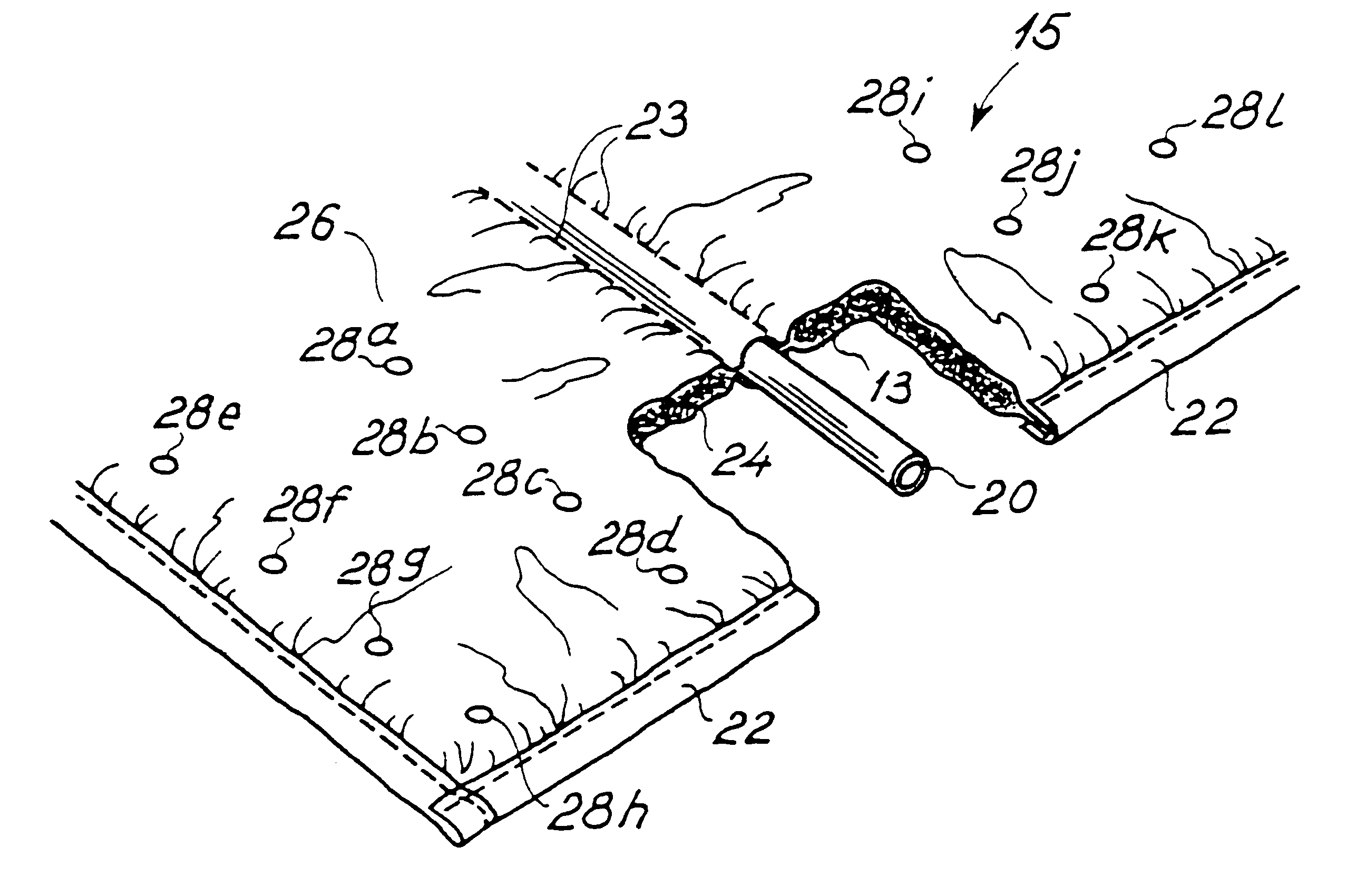
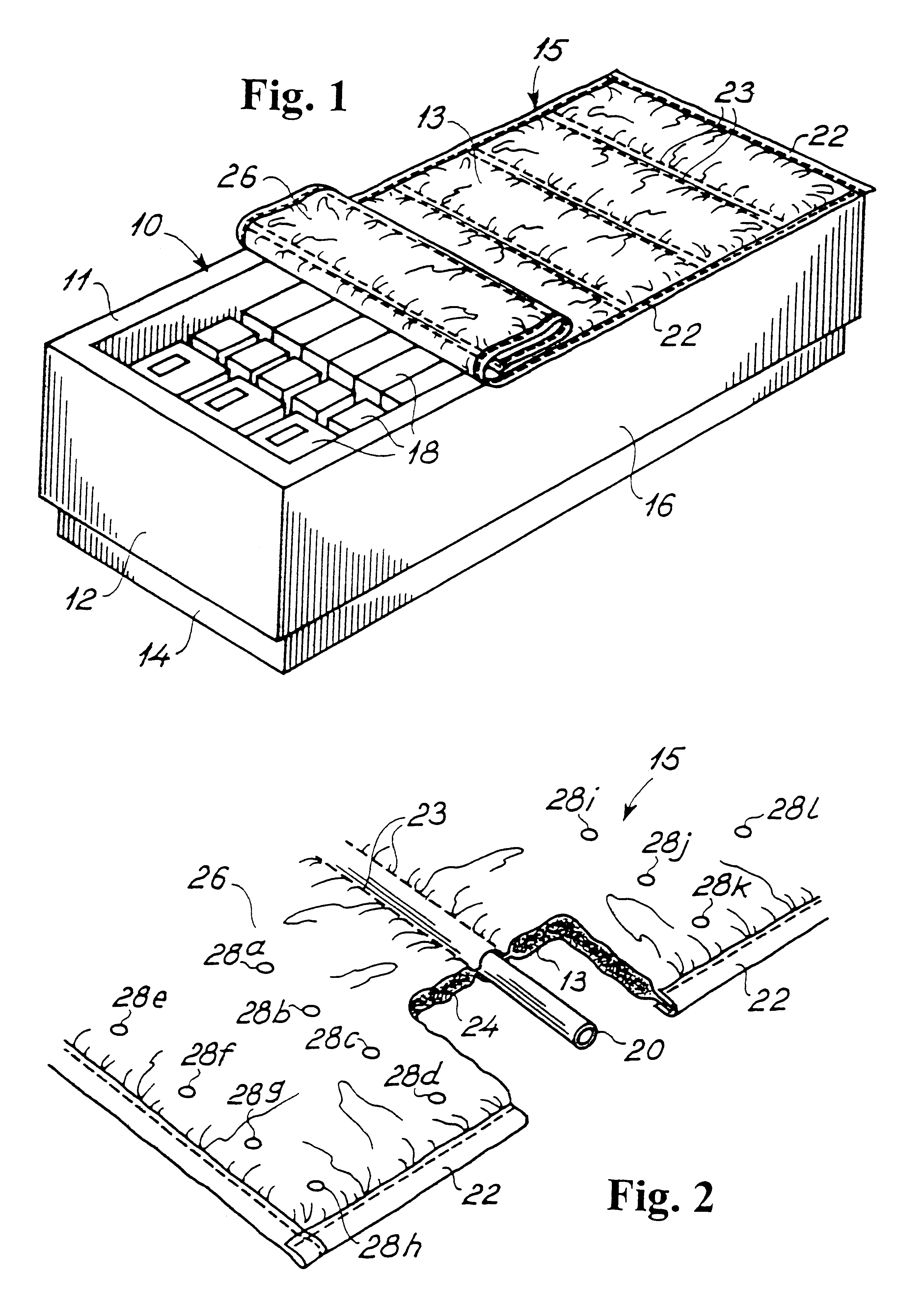
The preferred embodiment of the cover according to the present invention described above with reference to FIGS. 1 and 2, was made as follows.

The rectangular insulating cover 15 had the overall dimensions: length 1250 mm, width 910 mm, average thickness 5 mm, with 2 supporting tubular elements each having a diameter of approximately 10 mm and separated by a distance of 600 mm. The first supporting tubular 20 element placed at a distance of 325 mm from one edge of the insulating cover parallel to the axis of the supporting tubular elements and the second supporting tubular 20 element placed at a distance of 925 mm from said edge. The supporting tubular elements 20 were fixed using through-stitches 23 separated by 25 mm.

The outer foil was impermeable and made of the material PE and had an average thickness of 120 .mu.m. The inner foil was impermeable and made of the same materials as the outer foil and also had an average thickness of 120 .mu.m. The inner foil was perforated with hole...


PUM

PropertyMeasurementUnit
thicknessaaaaaaaaaa
thicknessaaaaaaaaaa
areasaaaaaaaaaa

Abstract

The insulating cover comprises a gas and water impermeable first foil (13) which defines a first circumferential outer rim, a gas and water impermeable second foil (26) substantially coextensive with said first foil (13) and defining a second circumferential outer rim. The first (13) and second foil (26) are joined together at the first and second outer circumferential rims of the first (13) and second outer circumferential rims of the first (13) and second foils (26), to define an enclosure between the first (13) and second (26) foils. A body of insulating material (24) is inserted in the enclosure. A plurality of supporting tubular elements (20) in co-planar relationship with said first (13) and second foil (26) provide a stiffness of the insulating cover (15) in axial direction of the plurality of supporting tubular elements (20) and flexibility of the insulating cover (15) in a direction perpendicular to the axial direction.

Description

This application claims priority from European Patent Application No. 98610027.9 filed Aug. 17, 1998.1. Field of the InventionThe present invention relates to an insulating cover for open cooling devices, such as refrigerators or deep freezers generally used in stores and supermarkets. In numerous cases refrigerators or deep freezers will not be covered over a longer period of time, e.g. stores selling products that need cooling to maintain freshness, rely on open refrigerators and deep freezers to provide easy accesses for the customers to the produce. However, in the closing hours of these stores the energy consumption can be greatly reduced by applying insulating covers to the openings of these cooling devices.2. Description of the Prior ArtThe conventional technique, used for reducing the energy consumption of cooling devices in the closing hours of stores and supermarkets, applies insulating covers to the openings of refrigerators or deep freezers. Chest refrigerators or chest ...

Claims


Application Information

Patent Timeline
Patent Type & Authority Patents(United States)
IPC IPC(8): A47F3/04
CPCA47F3/0469Y10T428/24033Y10T428/24041Y10T428/24744Y10T428/232Y10T428/239Y10T428/238Y10T428/237Y10T428/23Y10T428/233
Inventor CHRISTOFFERSEN, HENRIK
Owner COMBI THERM
Why Eureka
Try Eureka