Piezoelectric/electrostrictive device and production method thereof

a technology of electro-electrostrictive device and piezoelectric, which is applied in piezoelectric/electrostrictive/magneto-strictive device, piezoelectric/electrostriction/magneto-striction machine, instruments, etc., can solve the problems of low mechanical strength of material, low impact resistance, and heavy weight of actuator 21

Inactive Publication Date: 2001-12-11
NGK INSULATORS LTD
View PDF12 Cites 30 Cited by
  • Summary
  • Abstract
  • Description
  • Claims
  • Application Information

AI Technical Summary

Problems solved by technology

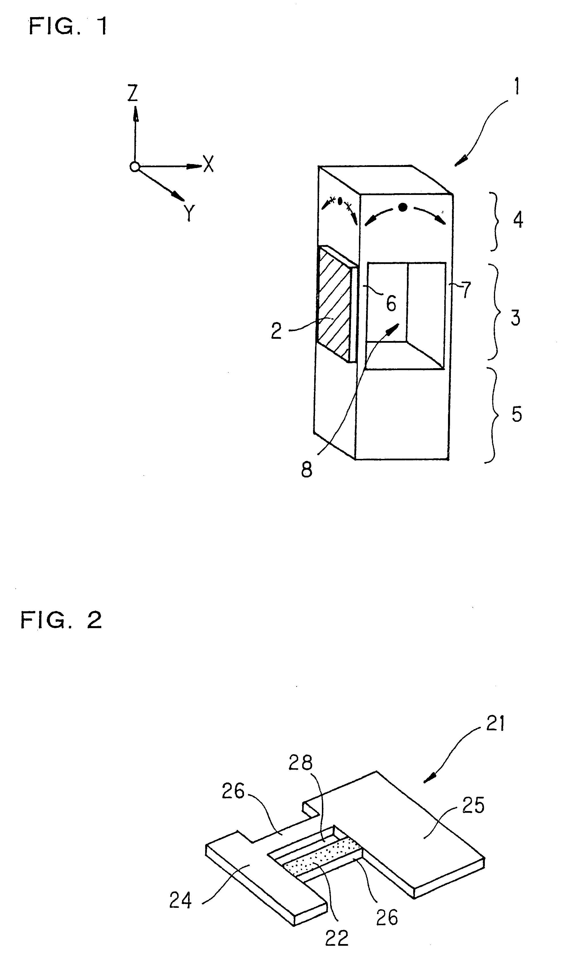
Furthermore, in the actuator 21, since all parts are constituted by a piezoelectric / electrostrictive material which is a brittle and relatively heavy material, there has been a problem in that the actuator 21 itself is heavy and it may easily be affected by a harmful vibration in operation (for example, a residual vibration or a noise vibration in high speed operation).
In addition, the material has low mechanical strength and is inferior in handling efficiency, impact resistance, and moisture resistance.
Furthermore, since it is unnecessary to use a filler, the efficiency of displacement based on the inverse piezoelectric effect or electrostrictive effect is not lowered.
Furthermore, a producing method of joining the respective component members prepared as different bodies is also possible, but it has a problem from the view point of reliability since damages or the like easily occur in the junctions, in addition to low productivity.

Method used


Image

  • Piezoelectric/electrostrictive device and production method thereof
  • Piezoelectric/electrostrictive device and production method thereof
  • Piezoelectric/electrostrictive device and production method thereof

Examples


Embodiment Construction

of Device

Finally, as one example of the applications of a device of the present invention, an example in which a device of the present invention is applied to displacement element for a light shutter will be described. "Light shutter" expressed in the present specification means a functional element which controls penetration and shielding of light by relatively displacing two shielding plates, and since it can perform ON / OFF control of light and light volume control, it can function as a light switch or a light aperture.

A light shutter of the present invention is a shutter in which at least one shielding plate of two shielding plates is attached to a movable portion of a device of the present invention.

For example, a light shutter 110 shown in FIGS. 20 (a), (b) is made of two units 111 A, 111 B equipped with devices of the present invention and shielding plates, and two shielding plates 113A, 113B are respectively attached to movable portions 114A, 114B of the devices, and they are...


PUM

PropertyMeasurementUnit
widthaaaaaaaaaa
widthaaaaaaaaaa
thicknessaaaaaaaaaa

Abstract

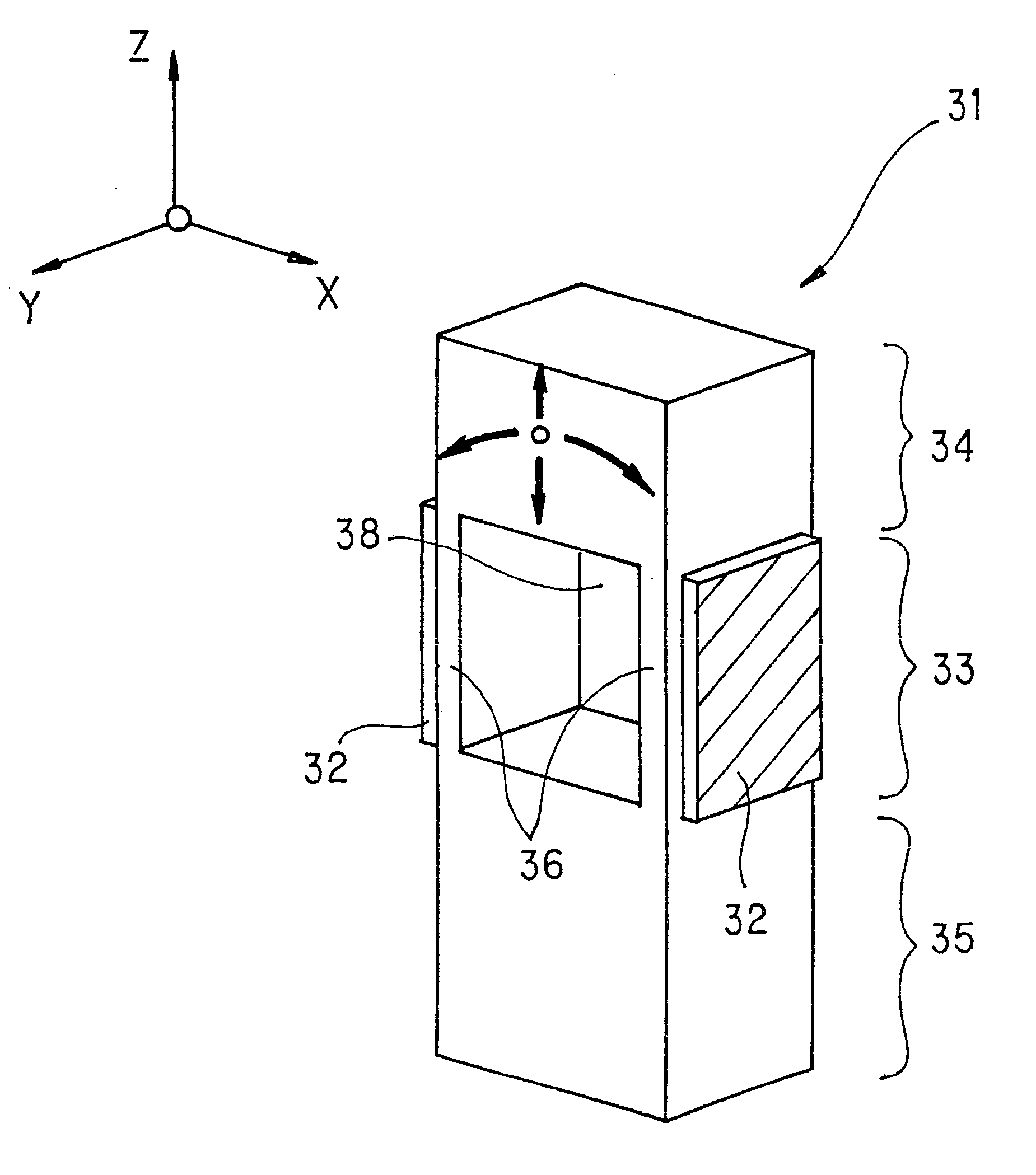
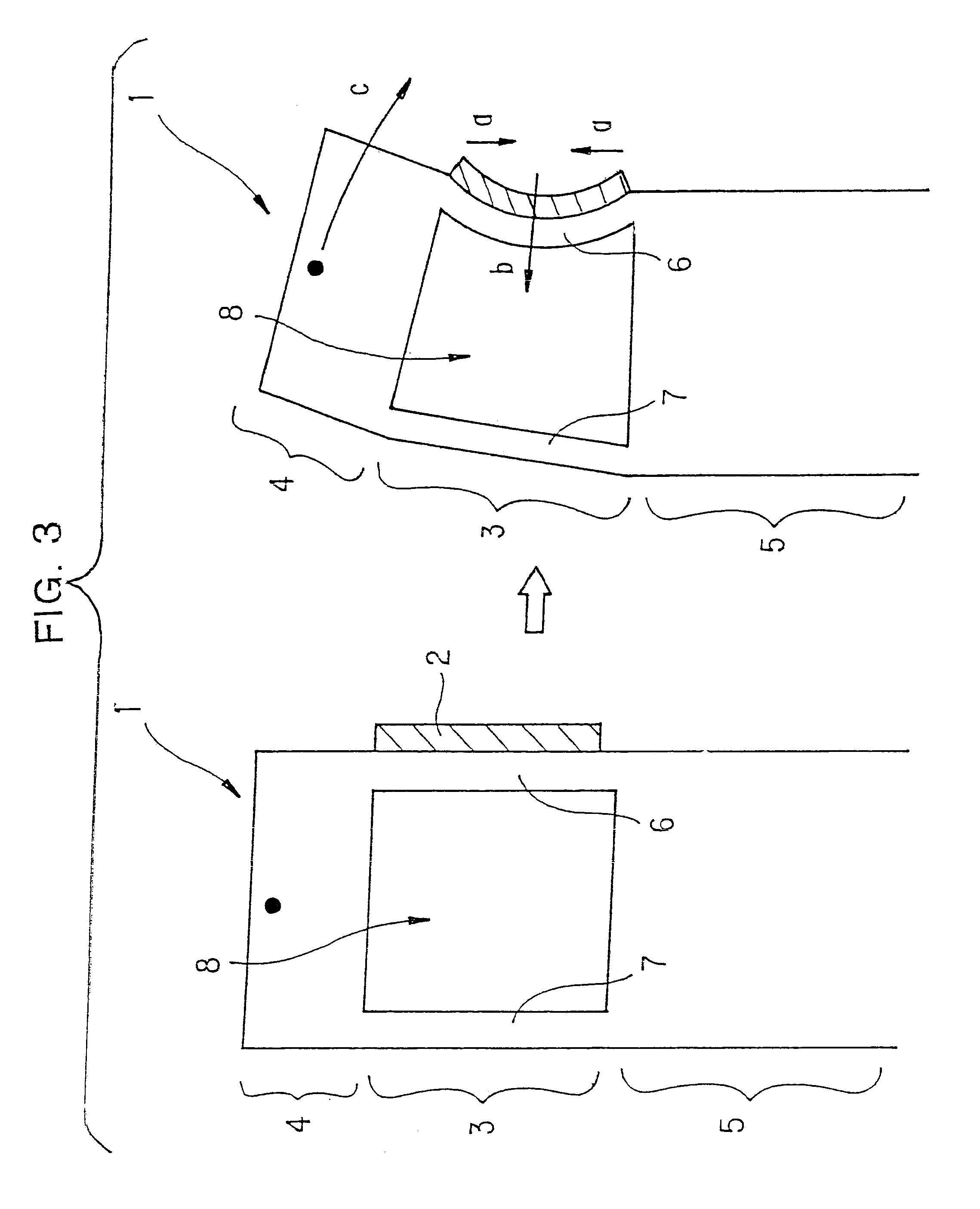
A piezoelectric/electrostrictive device includes: a driving portion which is driven by displacement of a piezo-electric/electrostrictive element, a movable portion which operates on the basis of a drive of the driving portion, and a fixed portion for supporting the above driving portion and movable portion. It has a driving portion including thin plates facing each other and a thin film piezoelectric/electrostrictive element formed on the surface of at least one of the thin plates, and the above fixed portion and the above movable portion are joined by the driving portion. In this piezoelectric/electrostrictive element, the movable portion can largely be displaced, and it is not easily affected by a harmful vibration in operation, and it is excellent in mechanical strength, handling efficiency, impact resistance, and moisture resistance.

Description

BACKGROUND OF THE INVENTION AND RELATED ART STATEMENTThe present invention relates to a piezoelectric / electrostrictive device having a movable portion which operates on the basis of displacement of a piezoelectric / electrostrictive element, or a piezoelectric / electrostrictive device which can detect displacement of a movable portion by a piezoelectric / electrostrictive element, and particularly relates to a piezoelectric / electrostrictive device which is excellent in strength, impact resistance, and moisture resistance and has a high amplitude efficiency and can largely operate the movable portion.Recently, in the fields of optical and magnetic recording, precisionmachining or the like, a displacement element which can adjust an optical path length or a position in sub-micron precision has been required, and the development of a displacement element which uses displacement based on the inverse piezoelectric effect or electrostrictive effect caused when voltage is applied to a piezoelec...

Claims


Application Information

Patent Timeline
Patent Type & Authority Patents(United States)
IPC IPC(8): H01L41/24H01L41/09G02B26/04G02B26/08H02N2/00
CPCG02B26/04G02B26/0858H01L41/0946H01L41/314Y10T29/43Y10T29/49798Y10T29/42Y10T29/49005Y10T29/49126H10N30/2043H10N30/074
Inventor HIROTA, TOSHIKAZUKIMURA, KOJITAKEUCHI, YUKIHISA
Owner NGK INSULATORS LTD
Why Eureka
Try Eureka