System and method for measuring pressure applied by a piezo-electric pump

a piezo-electric pump and piezoelectric technology, applied in the direction of machines/engines, liquid fuel engines, positive displacement liquid engines, etc., can solve the problem that high amplitude acoustic resonance has not been employed in disc-shaped cavities, and achieve the effect of effective and economical control of the operation of the disc pump and reducing pressur

Inactive Publication Date: 2012-02-09
KCI LICENSING INC
View PDF14 Cites 48 Cited by
  • Summary
  • Abstract
  • Description
  • Claims
  • Application Information

AI Technical Summary

Benefits of technology

[0011]In addressing measurement and control issues of tissue treatment systems, which may include a disc pump or micro-pump, the principles of the present invention may be utilized to measure the pressure being generated by the disc pump to more effectively and economically control the operation of the disc pump. The disc pump includes an actuator that vibrates within a cavity to generate a radial pressure wave to provide a reduced pres

Problems solved by technology

However, high amplitude acoustic resonance has not been employed within disc-sh

Method used


Image

  • System and method for measuring pressure applied by a piezo-electric pump
  • System and method for measuring pressure applied by a piezo-electric pump
  • System and method for measuring pressure applied by a piezo-electric pump

Examples


Embodiment Construction

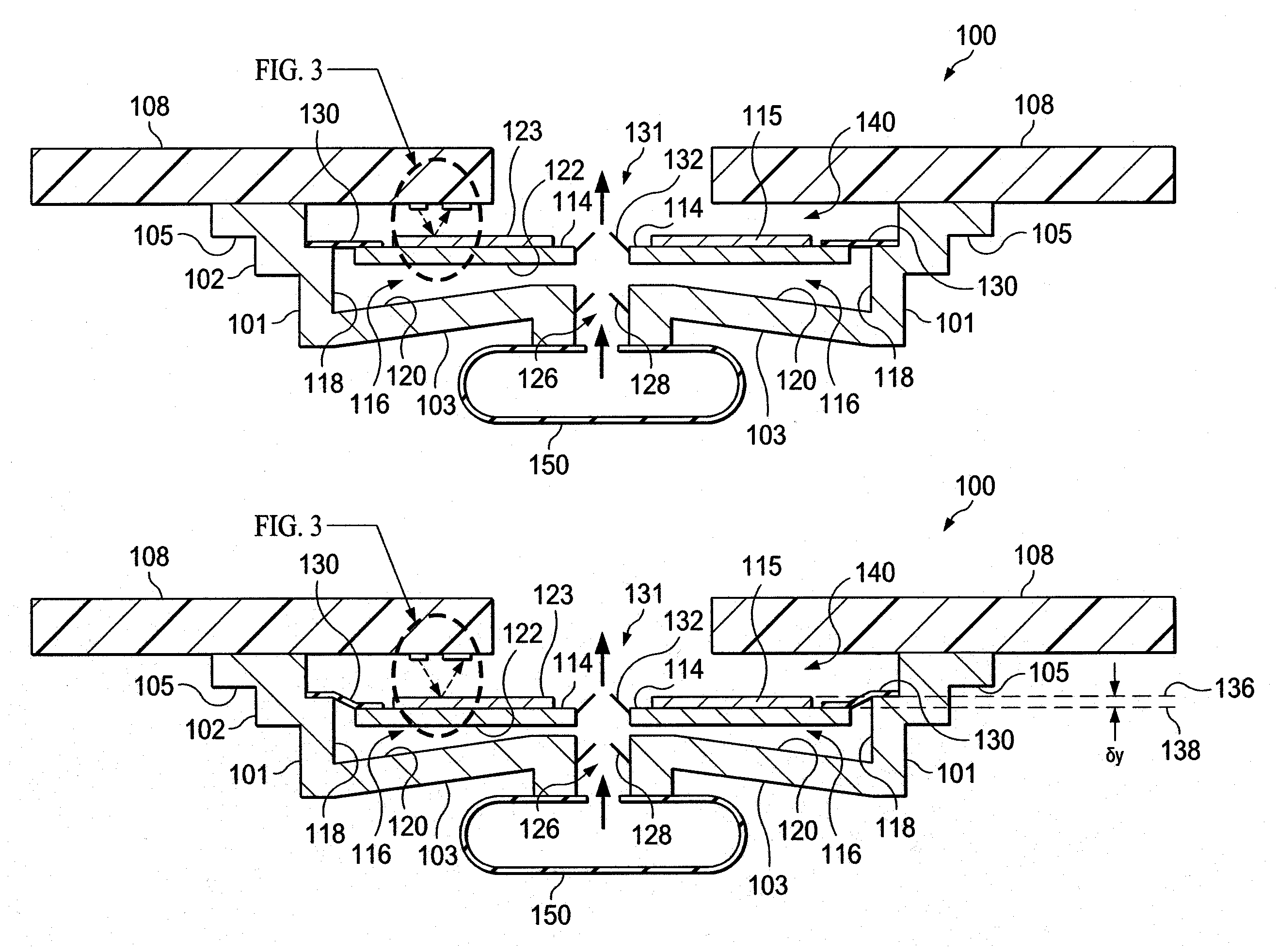
[0028]FIGS. 1A and 1B are illustrations of a cross-section view of an illustrative disc pump 100 in accordance with illustrative embodiments. As shown, the disc pump 100 may include a pump housing 102 having a substantially elliptical shape including a elliptical wall 101 closed at one end by a base wall 103 and mounted at the other end by legs 105 attached to a circuit board 108 or other substrate to support the pump housing 102. The elliptical wall 101, the legs 105, and base wall 103 together form the pump housing 102. The pump 100 further comprises a pair of disc-shaped interior plates 114, 115 supported within the pump 100 by a ring-shaped skirt 130 affixed to the elliptical wall 101 of the pump body. The internal surfaces of the elliptical wall 101, the base wall 103, the interior plate 114, and the ring-shaped skirt 130 form a cavity 116 within the pump 100. The internal surfaces of the cavity 116 comprise a side wall 118 which is a first portion of the inside surface of the ...


PUM


Abstract

A system and method for measuring the pressure provided by a disc pump is disclosed. The disc pump comprises an actuator mounted within the disc pump on a flexible skirt that allows the actuator to oscillate for generating air flow through the cavity of the pump and allows the actuator to be displaced with increasing pressure to a load. The actuator moves from a rest position when air begins flowing through the cavity to a biased position when the load is fully pressurized or depressurized depending on the direction of fluid flow through the cavity. The pump further comprises a sensor which measures the displacement of the actuator at any position between the rest position and the biased position as fluid begins flowing through the cavity to pressurize or depressurize the load. The pressure being delivered by the disc pump is determined as a function of the displacement of the actuator.

Description

CROSS-REFERENCE TO RELATED APPLICATIONS[0001]This application claims the benefit of U.S. Provisional Application No. 61 / 371,954, filed Aug. 9, 2010, and is hereby incorporated by reference.BACKGROUND[0002]1. Field of the Invention[0003]The illustrative embodiments of the invention relate generally to a pump for fluid and, more specifically, to a pump in which the pumping cavity is substantially elliptical in shape having end walls and a side wall with an actuator disposed between the end walls. The illustrative embodiments of the invention relate more specifically to a disc pump having a valve mounted in the actuator and / or one additional valve mounted in one of the end walls.[0004]2. Description of Related Art[0005]The generation of high amplitude pressure oscillations in closed cavities has received significant attention in the fields of thermo-acoustics and pump type compressors. Recent developments in non-linear acoustics have allowed the generation of pressure waves with higher...

Claims


Application Information

Patent Timeline
IPC IPC(8): F04B53/00
CPCF04B43/046F04B2205/09F04B2205/03F04B49/065
Inventor TOUT, AIDAN MARCUSLOCKE, CHRISTOPHER BRIAN
Owner KCI LICENSING INC
Why Eureka
Try Eureka