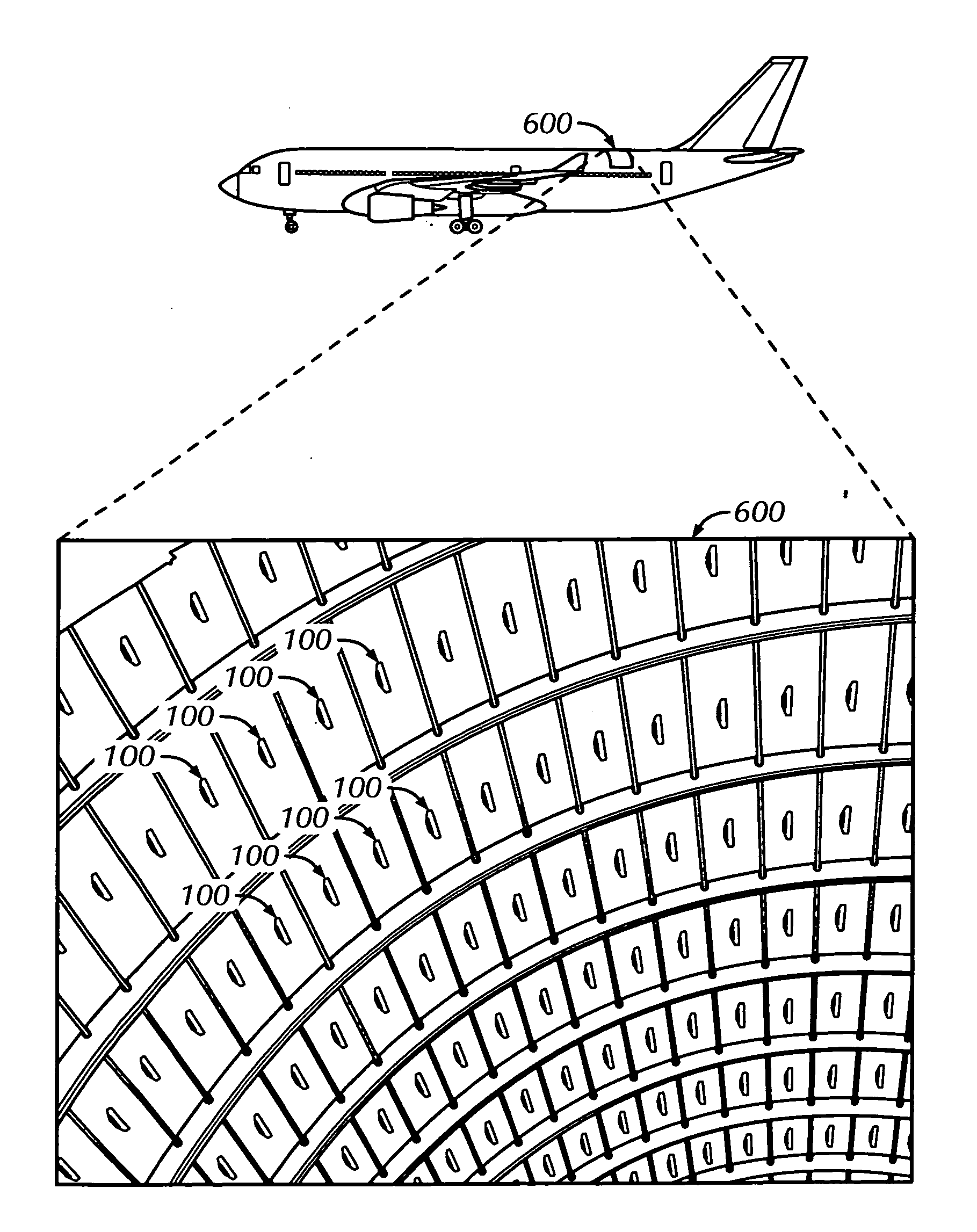
[0009]The invention, as a key component of structural
radar based SHM systems, as for example SHM, is intended to be applied on already existing structures or components and also on new ones, in order to make possible the following objectives: a) reduce direct maintenance costs and labour effort associated with the use of common
non destructive methods to assess
structural integrity, b) simplify and optimize future maintenance models and make possible real
Condition Based Maintenance (CBM) in order to achieve considerable reduction of scheduled maintenance (especially important for aircraft operators or (airliners) and aircraft down time, c) increase
operational performance and structure availability at minimal cost for the
end user, d) increase or enhance
transportation safety especially for critical structures in critical service environments, regimes and missions,
critical load cases or service regimes (like
spacecraft and aircraft for example), e) increase
quality assurance of the final product—(sub)structure or component, f) improve and make possible real in situ
structural health monitoring of Damage Tolerant Structures (DTS), for example for upcoming new generation aircraft, g) measure structural
ageing and acquire structure
operational performance data, the input necessary for assessment of consumed structure life, prognosis of
remaining life and possible extension of aging structures or aircraft, h) optimize (for shape and
mass) future structures by use of Fully Stressed Design (FSD) approach through use of operational
stress distribution maps obtained in a plurality of real service environments (important input for design and stress engineers), i) identify
critical structure areas during service of the structure in real environments, j) provide additional added value to future structures by development of intelligent
self sensing and self maintainable structures, k) reduction of
Time To Market (TTM) and total life cycle cost through cancelling of all common
Non destructive Testing, Evaluations and Inspections (NDT / NDE / NDI), taking place, for example, during fatigue certification tests or critical assembly phases, make easier and more precise identification of real causes of possible structural damages or defects so the most effective countermeasures would be selected timely and directed toward solutions of real problems and not just temporary solution “patches”, m) significantly reduce actual work effort for maintenance providers associated with the maintenance of structures or assessment of its
structural integrity, n) have valuable information about structure integrity, consumed or
remaining life at all moment (important information for assurance or leasing companies, structure purchasers, retailers or maintenance providers), etc.
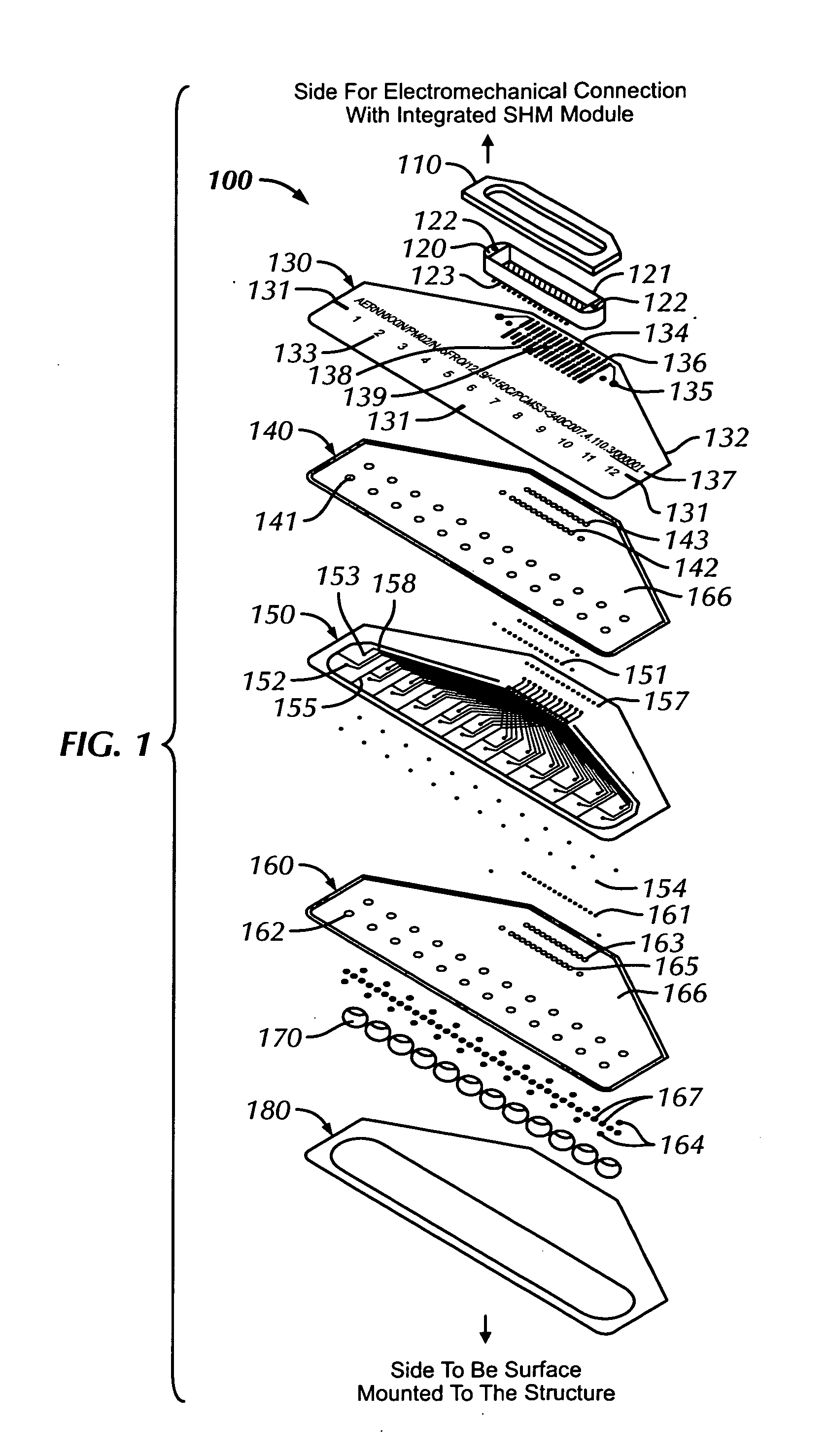
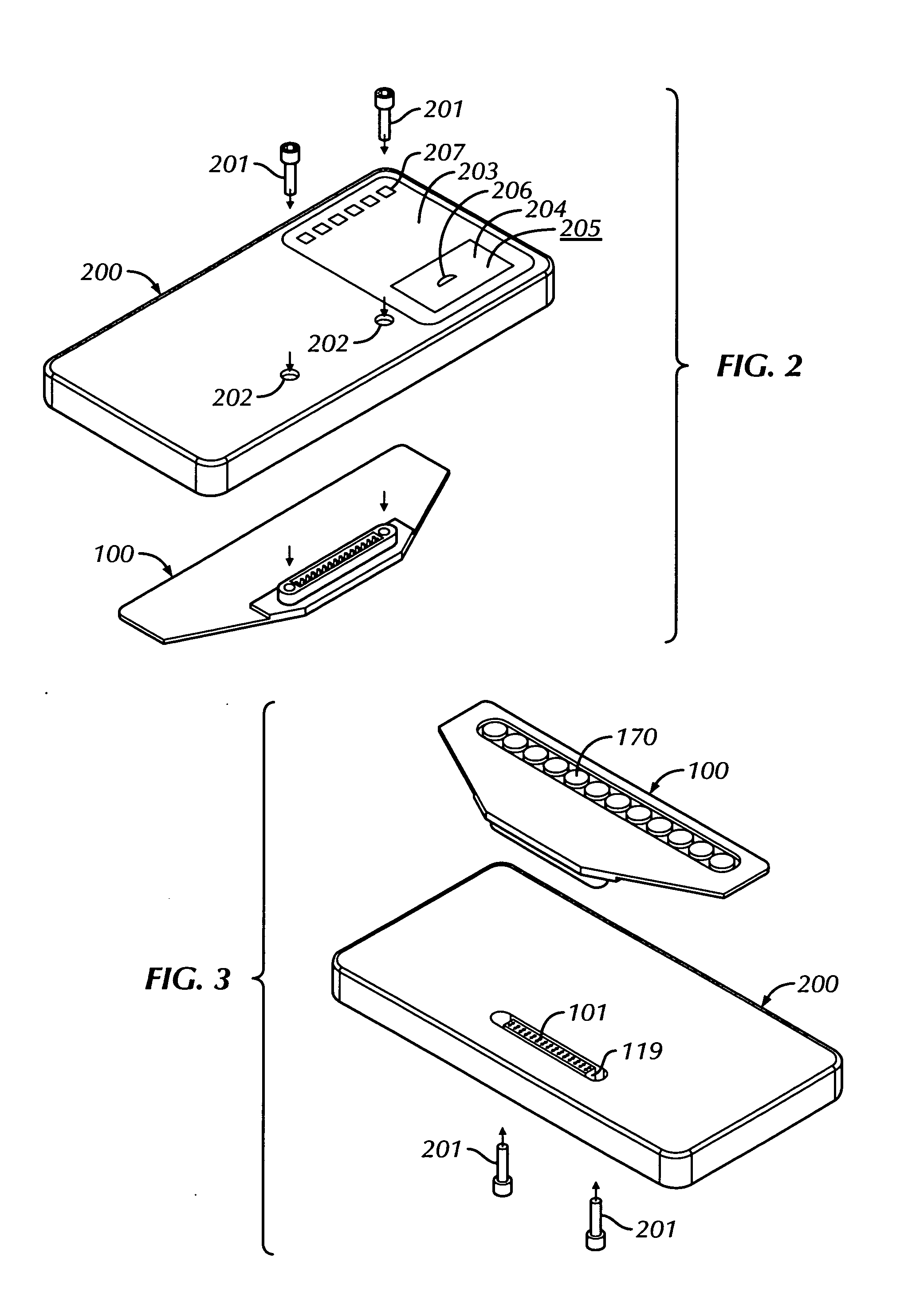
[0014]In still another embodiment, the PhA transducer comprises at least one integrated multi-pinned electromechanical connector, where each comprise at least two threaded holes for mechanical fastening with the SHM device by screws. Further more, integrated PhA transducer is flexible enough to be bonded onto a curved surface and once bonded stiff enough to carry above corresponding SHM device, supporting associated transferred inertial loads, assuring at all moment during structure service life, reliable electromechanical
interconnection.
[0016]In a further embodiment, the PhA transducer comprises an easily perceptible
horizontal and vertical alignment markers allowing to verify the correct positioning during bonding procedure, of the center lines of the piezo-electric discs array of the transducer onto the host structure and in accordance with other structure features, like holes, stiffeners, edges, etc.
[0018]In another preferred embodiment there is presented a method for obtaining data about structural health, integrity, condition or structural performance from the structure by use of the disclosed SHM
system, comprised by plurality of in situ distributed integrated phased array transducers and SHM devices, wherein each one of these SHM sets is capable to cover a certain inspection area, defined by a host structure features and SHM set performance, where the SHM methodology comprises the hereinafter detailed steps. The first step is proper preparation of surface for bonding in order to permanently and properly install integrated
phased array transducer, preferably by bonding, on a specific inspection sector of the host structure. Then, it is necessary to repeat the previous step for each integrated PhA transducer of the entire SHM system. Than follows attachment of the SHM electronic device(s) with compatible connector above the PhA transducer(s), proper electromechanical connection and secure for untightening. Electrical powering of the SHM device(s) and activation is necessary in order to perform by each SHM device signal generation,
signal acquisition, signal conversion,
signal conditioning, signal triggering, high speed channel
multiplexing, etc. Further more,
digital signal processing is directly performed by SHM devices where this
processing may include
signal averaging, signal de-noising, time and
frequency filtering, calculation of attenuations, wave velocities,
time of flight tables, calculation of temperature and
stress effects, etc. The step further is entrance with prepared signals and
calculated data from the previous step into SHM algorithms for image reconstruction embedded in the SHM devices in order to generate maps for SHIM,
Stress Distribution Maps, Stiffness Distribution Maps, Temperature Distribution Maps, Deformation Distribution Maps, Vibration Distribution Maps,
Impact Detection Maps, Leakage Maps, Material characteristics and / or structure
mass loss maps, wherein needless data is erased in order to make free place to store signal from subsequent acquisitions. Then follows the transfer of generated maps by wires or / and wirelessly from each SHM device to at least one
on board receiver device with display and proper
visualization tools installed. Next in the procedure is an assembly and projection of all received maps from each inspection sector and SHM device into a 3D model of the structure, by placing each map to a corresponding position inside the 3D model in order to provide easier interpretation and analysis of entire structure integrity,
stress distribution, temperature distribution, stiffness distribution or other useful data like
impact or leakage detection. Optional step could be transfer of new versions of DSP tools, image reconstruction algorithms or
software for embedding, from
receiver device to each SHM device by use of the same communication pathways as used for transfer of the SHM maps in order to install or embed new DSP tools, algorithms or
software on each SHIM device and than continue the KIM methodology with improved
software features.


