Drying device

Inactive Publication Date: 2001-12-25
FUJIFILM HLDG CORP +1
View PDF7 Cites 2 Cited by
  • Summary
  • Abstract
  • Description
  • Claims
  • Application Information

AI Technical Summary

Benefits of technology

FIG. 5 is a schematic view showing a general compositi

Problems solved by technology

Consequently, it is difficult to control the dew point of a gas flow fed into each of the heli

Method used


Image

  • Drying device
  • Drying device
  • Drying device

Examples


example 1

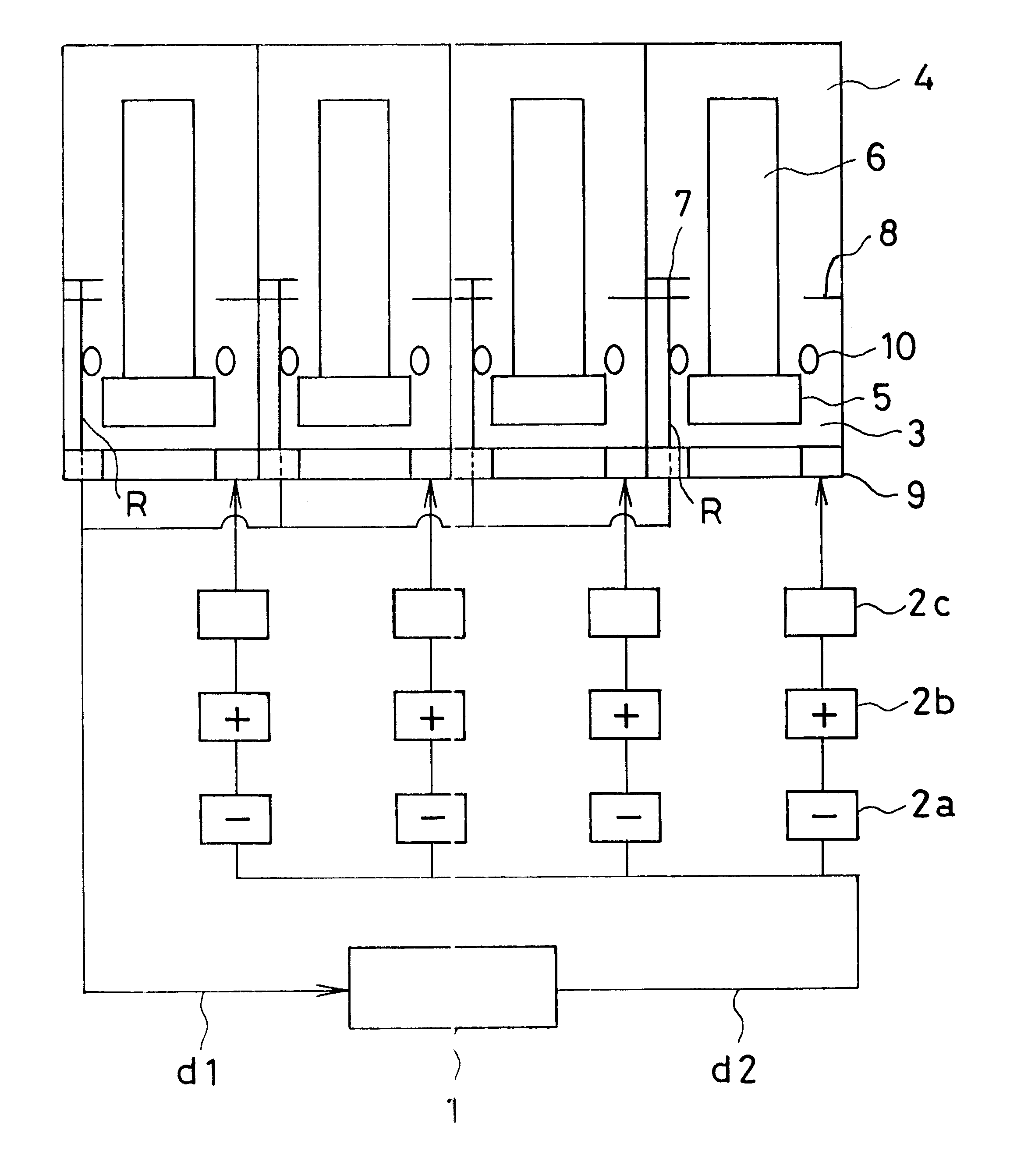
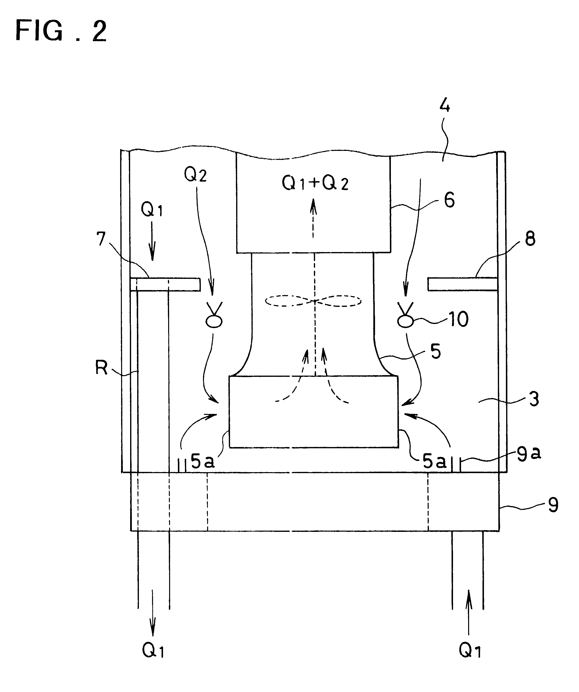
The following explanation concerns the outline of a drying device of Example 1 shown in FIG. 1. A dehumidifying facility 1 employed communicates with a duct d1 which further communicates with a drying room including a helical dryer 6 therein, and dehumidifies an air flow flowing therein out of a drying room to produce a dehumidified air flow. Then, the dehumidified air flow runs out of the dehumidifying facility 1 into a duct d2. The duct d2 has four branches. First branch connects through a duct to an air cooler 2a, an air heater 2b and a humidifier 2c successively in this order, and communicates with an annular blowing chamber 9.

Accordingly, the dehumidified air flow branched at a junction and flowing into the first branch is cooled in the air cooler 2a, heated in the air heater 2b, and humidified in the humidifier 2c before flowing into the annular blowing chamber 9. The air flow after flowing into the annular blowing chamber 9 is humidified, but consists of an air flow having de...

example 2

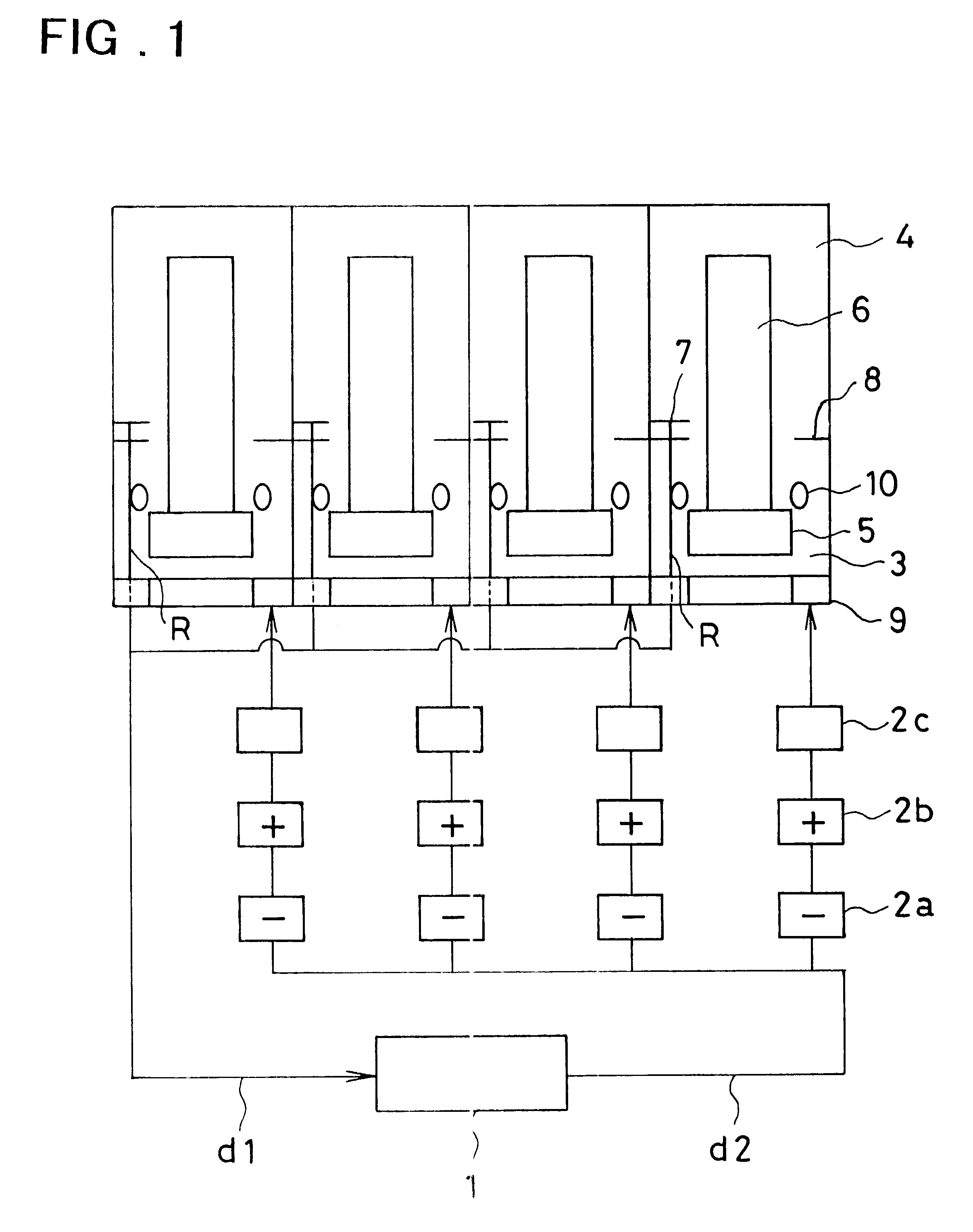
The drying room and the blower-installing room in the drying device of the above Example 1 may have an inner structure as shown in FIG. 3. FIG. 3 is a sectional view taken in the longitudinal direction of the helical dryer showing flowing room of an air flow having a depressed dew point, drying room and neighborhood thereof in another exemplary drying device of the present invention.

The air flow having a depressed dew point flows through a duct into the influent room of the air flow having a depressed dew point. The influent room of the air flow having a depressed dew point is formed by partitioning a cylindrical room, which includes therein an approximately cylindrical axial-flow blower 33 which connects to a helical dryer 34 at the open end of the dryer and enables to feed a drying air flow into the helical dryer thereby. A partition board 31 extends in the radial direction thereof, thereby partitioning the cylindrical room axially in two parts.

Explaining more in detail, the parti...

example 3

In the drying device of the above described Example 1 shown in FIG. 1, all of drying air flows fed by four drying devices are changed into the mixture of the directly circulated air flow and the air flow having the depressed dew point. However, drying air flow(s) fed by limited (as a limited number of) helical drying device(s) can be made selectively to change into the mixture of the directly circulated air flow and the air flow having the depressed dew point. Namely, depending on the predetermined condition of drying temperature and humidity, the above admixed air flow can be fed on a drying object by the limited, specified helical dryer(s) installed in the limited (specified) drying room(s) in which drying can be carried out with a large degree of freedom.

An example of this case will be explained below in reference to FIG. 4. FIG. 4 is a schematic view showing a general disposition (or arrangement) of units contained in an exemplary drying device of the present invention. This dry...


PUM


Abstract

A drying device in which temperature and humidity of a gas flow fed into each of plural helical dryers in the form of a cylinder (i.e., temperature and humidity of an exhausted gas flow) can be each controlled independent of the other dryers. The drying device, is equipped with a casing. The casing includes therein at least a helical dryer 6 in the form of a cylinder for exhausting a drying gas flow fed therein out of gas distributed on its outer periphery to feed on a drying object, and an axial-flow blower 5 connected to an entrance side of the helical dryer for inspiring a gas flow exhausted out of the helical dryer into the casing inside the same casing and feeding into the helical dryer again to circulate said gas flow, in which a part of a gas flow inspired by the axial-flow blower serves as a gas flow having a depressed dew point which results from splitting a gas flow exhausted out of the helical dryer and depressing the dew point of the split gas flow in a dehumidifying facility 1 located outside the casing.

Description

The present invention relates to a drying device, more particularly, to a device for drying the surface necessary to be dried by feeding a gas flow, especially by multi-steps, to an object necessary to be dried (a drying object), which has a surface desired to be dried, such as a long web-shaped drying object with a coating solution coated thereon and the like.As a device for drying the surface necessary to be dried by feeding a drying gas flow to a long belt-shaped drying object having the surface necessary to be dried such as coating film and the like, for example, those disclosed in JP-B-48-44151 / 1973, JP-B-51-22115 / 1975, JP-A-7-289971 / 1995 and JP-A-9-152274 / 1997 (the term "JP-A" as used herein means a Kokai-Publication, i.e., "unexamined laid-open Japanese patent application" and the term "JP-B" as used herein means a Kokoku-Publication, i.e., "examined published Japanese patent application") are known.In a conventional drying device, as disclosed in, for example, JP-A-7-289971 / ...

Claims


Application Information

Patent Timeline
IPC IPC(8): F26B21/08F26B13/10F26B21/06G03D15/02
CPCF26B13/10F26B21/06F26B21/08
Inventor FUKUHORI, SHINJIITO, HIDETOMO
Owner FUJIFILM HLDG CORP
Why Eureka
Try Eureka