Mechanical torque amplifier

a torque amplifier and mechanical technology, applied in the direction of wrenches, drilling casings, drilling pipes, etc., can solve the problems of insufficient power to release, affecting the operation of the rig, and requiring a larger and more expensive tong to perform the job,

Inactive Publication Date: 2002-01-01
TESCO HLDG I
View PDF4 Cites 116 Cited by
  • Summary
  • Abstract
  • Description
  • Claims
  • Application Information

AI Technical Summary

Problems solved by technology

Another problem with conventional hydraulic power tongs is that the tongs may not provide sufficient power to release (break out) a connection that is made up to a high torque value.
Generally, the greater the torque required for a given job, the larger and more expensive the tong required to perform the job.
A related factor is that the space available on most drilling or workover rigs is limited, and it is desirable to keep the equipment size as small as possible while still maintaining the ability to perform the required work.
Application of torque through the contraction or expansion action of the piston-cylinder assembly applies a controlled, linear change in the torque, as contrasted with the uncontrolled, rapid change in torque that occurs when torque is applied solely by the tong motor.

Method used


Image

  • Mechanical torque amplifier
  • Mechanical torque amplifier
  • Mechanical torque amplifier

Examples


Embodiment Construction

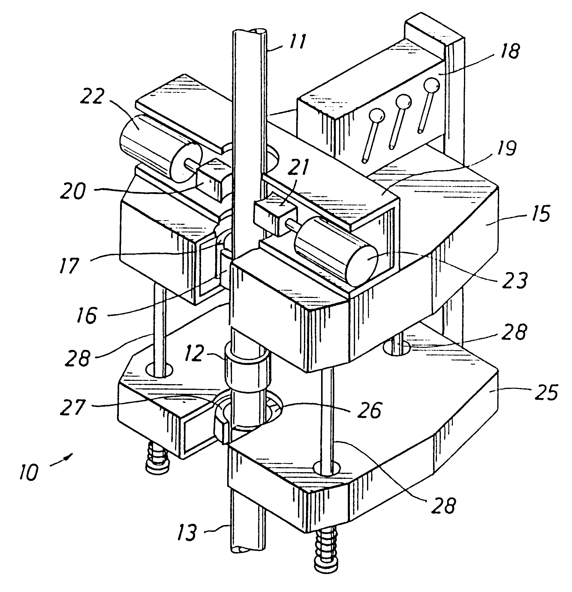
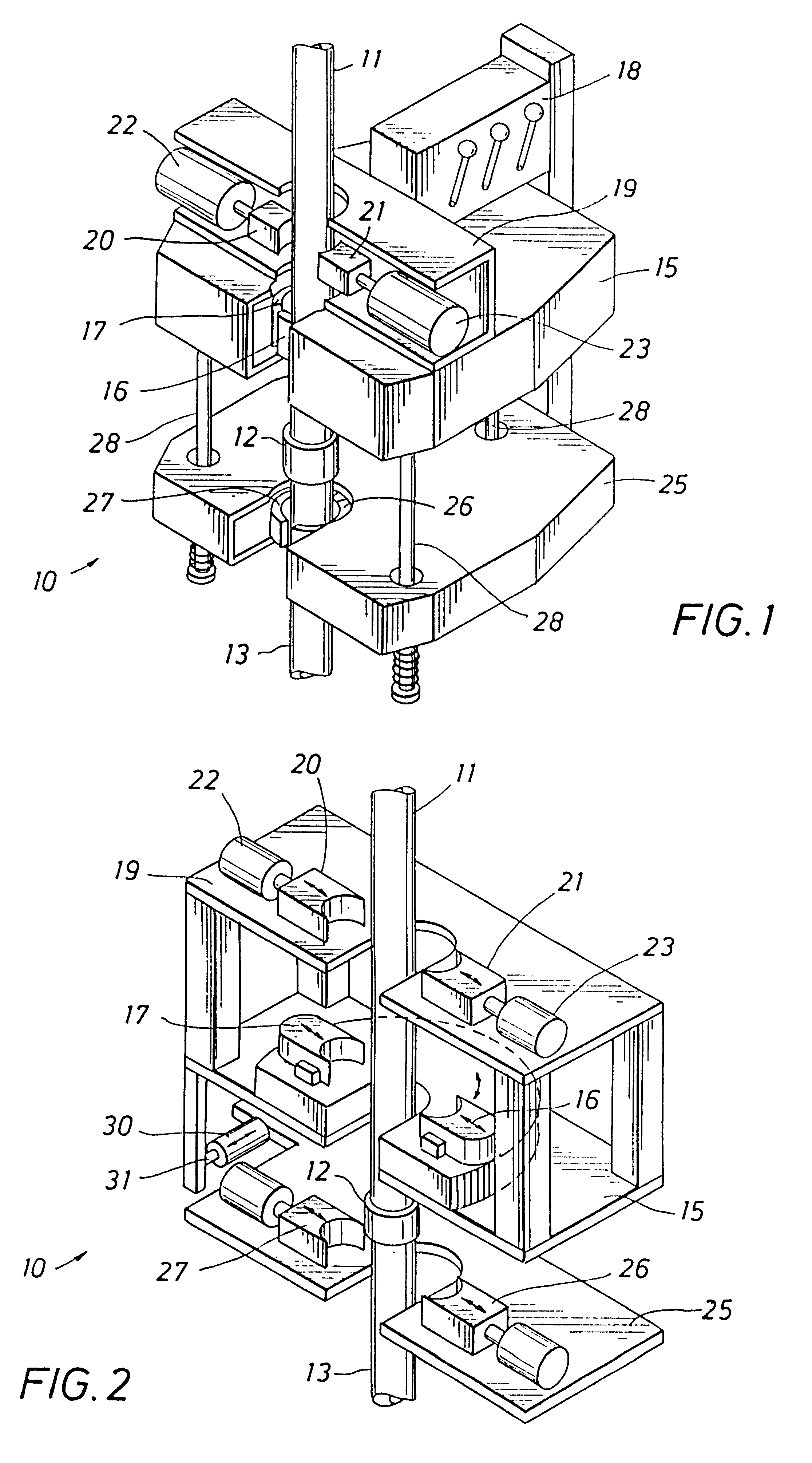
The tong assembly of the present invention is indicated generally at 10 in FIG. 1. FIG. 2 schematically illustrates the major operative components of the assembly 10. Similar reference characters in FIGS. 1 and 2 signify the same or similar components. The assembly 10 is illustrated in a position about a pipe string segment comprised of an upper pipe joint 11, a coupling assembly 12, and a lower pipe joint 13. A primary rotary power section 15 of the assembly 10 is employed to rotate the pipe string. The assembly 10 engages the pipe joint 11 with jaws 16 and 17 carried in the rotary and adapted to grip and hold the pipe joint while the rotary turns. The jaws 16 and 17 operate conventionally and are designed to be selectively moved radially into and out of engagement with the pipe by circumferential displacement of camming surfaces formed between the jaws and the tong rotary. An operator-managed hydraulic system 18 controls the gripping, rotation, and power application of the tong se...


PUM


Abstract

A power tong system is used to make up and break out threaded pipe connections. Rotary power tongs are connected to an integral backup tong through an extendable hydraulic cylinder and rod. A brake is secured to the rotary tong to selectively hold the pipe stationary relative to the rotary tong. When rotation of the pipe by the rotary tong ceases, the brake is applied, and the cylinder and rod are actuated to angularly displace the power tongs and the backup tong to apply a torque force to the pipe connection disposed between the power tongs and the backup. A resulting torque force is obtained that is greater than the maximum torque that can be exerted by the rotary tong acting alone. The system may also be deployed to apply and hold precise torque forces on the pipe connections. When used to obtain a makeup torque below the maximum rated rotary tong output, the rotary tong is regulated to limit its torque output. When the limited torque is reached, the brake is applied and the cylinder and rod are actuated to apply a smooth, closely controlled increase in torque to the connection. The final torque level may be held constant for a desired length of time. In both the high and low torque applications, the brake prevents the rotary tong from being turned backwardly by the increased torque force applied by actuation of the rod and cylinder assembly. Operation of the system may be manually or automatically controlled.

Description

1. Field of the InventionThe present invention relates to the application of torque forces to an object engaged by a wrench. More particularly, the present invention relates to the application of angular torque forces to a pipe that is being threadedly engaged to, or disengaged from, another pipe with the use of a hydraulic power tong.2. Description of the Prior ArtLong strings of joined pipe sections are required for the drilling and completion of oil and gas wells. The pipe string is assembled by screwing together pipe sections, or "joints," typically 30-40 feet in length to make a long, continuous string of pipe that is lowered into the well as the joints are added. The joints are typically equipped with male "pin" threads at one pipe end and female "box" threads at the other pipe end. The string is extended by screwing the pin of the joint being added into the box at the top of the string.During the early days of the drilling industry, the pipe string was screwed together in a t...

Claims


Application Information

Patent Timeline
Patent Type & Authority Patents(United States)
IPC IPC(8): E21B19/16E21B19/00
CPCE21B19/164E21B19/163
Inventor TORRES, CARLOS A.
Owner TESCO HLDG I
Why Eureka
Try Eureka