Apparatus and method for crystallization

a crystallization method and apparatus technology, applied in the field of apparatus and a method for crystallization, can solve the problems of undesired scaling, insufficient agitation of the crystallization area located in the bottom portion of the dtb vessel, and inability to adequately agitate the crystallization area in the vessel

Inactive Publication Date: 2002-01-01
AJINOMOTO CO INC
View PDF9 Cites 7 Cited by
  • Summary
  • Abstract
  • Description
  • Claims
  • Application Information

AI Technical Summary

Problems solved by technology

However, since conventional DTB crystallizers agitate the slurry so as to allow no influence from the agitated flow to the classification portion, the crystallization area located in the bottom portion of the DTB vessel can not be sufficiently agitated when the slurry contains crystals with large particle diameters.
This is a significant problem which occurs when conventional DTB crystallizers crystallize slurries containing crystals with large diameters.
Further, when the slurry needs to be strongly agitated, such as when the slurry is highly concentrated or the slurry needs to be perfectly mixed, it is more difficult to sufficiently agitate the crystallization area in the vessel.
In such a case, since the concentration of the slurry in the crystallization area located in the bottom portion of the vessel becomes high, crystals are deposited which readily causes undesired scalings thereof.
On the contrary, if the slurry is strongly agitated so as to avoid the scaling of the crystals, the classification portion is influenced by the agitation effects and, therefore, it becomes impossible to obtain the classification effects.
Thus, it has been difficult to avoid both problems.
However, the space between the plate baffles might be too small to manufacture an actual apparatus when employing the number of the plate baffles determined by the above manner.

Method used


Image

  • Apparatus and method for crystallization
  • Apparatus and method for crystallization
  • Apparatus and method for crystallization

Examples


Embodiment Construction

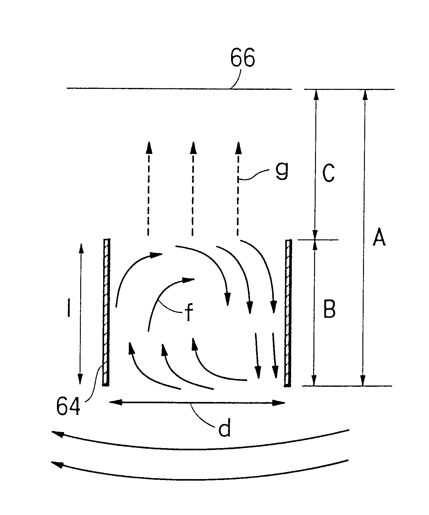
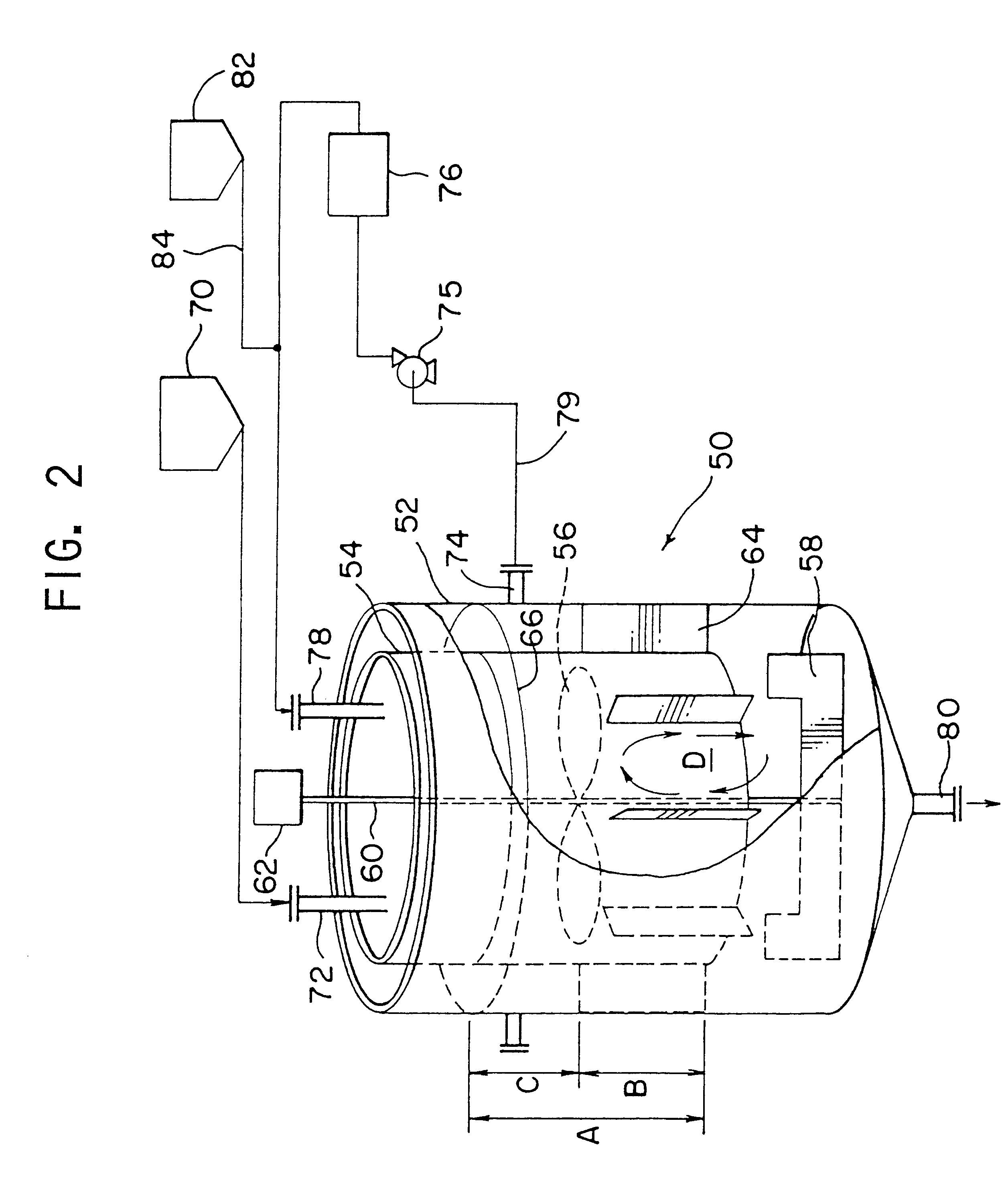
The apparatus for crystallization in accordance with the present invention was applied to slurry containing sodium glutamate, and the sodium glutamate was continuously crystallized. The particle diameter of the crystals to be classified was 300 micrometers, and the respective values of the components of the apparatus for crystallization were determined based on the manners explained above. Namely, the crystallization vessel 52 had a diameter of 160 mm and a height of 1850 mm, the tube baffle 54 had a diameter of 1200 mm and a height of 1310 mm, the classification portion A had a height of 1090 mm, the buffer portion B had a height of 600 mm, the gravitational settling portion C had a height of 490 mm, the plate baffle 64 had a height of 600 mm and a width (or a radial length of the classification portion) of 200 mm, and twelve of the plate baffles were spaced equally from each other. The first agitating fan 56 was a screw-type fan and the second agitating fan 58 was an anchor-type f...


PUM

PropertyMeasurementUnit
particle diametersaaaaaaaaaa
particle diameteraaaaaaaaaa
particle size distributionaaaaaaaaaa

Abstract

An apparatus for crystallization, which contains a crystallization vessel, a seed supplying device, a feed solution supplying device and a tube baffle disposed within the crystallization vessel. The tube baffle is provided with a crystallization portion in an inner area and a lower area thereof, and the tube baffle and the crystallization vessel define a classification portion there between. The apparatus further contains an agitating fan for agitating the seed crystals and the feed solution, and a plurality of plate baffles disposed within the classification portion which define a buffer portion and a gravitational settling portion. The apparatus further contains a device for generating a rising velocity of a slurry containing fine crystals in the gravitational settling portion by discharging the slurry so that the rising velocity of the slurry is greater than a settling velocity of the fine crystals and an outlet for discharging the crystallized material.

Description

1. Field of the InventionThe present invention relates to an apparatus and a method for crystallization, and, in particular, to an apparatus and a method which can produce large crystals by removing fine crystals by classification.2. Description of the BackgroundIn the field of crystallization, an apparatus for crystallization is known which can produce crystals having relatively large particle diameters by removing fine crystals using a classification. For example, a draft-tube baffled (DTB) crystallizer, and a Krystal-Oslo crystallizer are known.A conventional DTB crystallizer is described below with reference to FIG. 1. Reference numeral 1 designates a DTB vessel, and draft tube 2 is disposed across an entire center area within DTB vessel 1. Agitating fan 4 is disposed under draft tube 2, and fan 4 is rotatably driven through shaft 6 by motor 8 provided on DTB vessel 1. The lower portion of the center area of the DTB is open so as to enable it to work as baffle. Outer cylindrical...

Claims


Application Information

Patent Timeline
Patent Type & Authority Patents(United States)
IPC IPC(8): B01D9/00
CPCB01D9/0004B01D9/0036B01D9/02
Inventor MIYAHARA, ICHIROKITAMURA, TATSUOYOKOYAMA, MASATOKOKO, TAKASHI
Owner AJINOMOTO CO INC
Why Eureka
Try Eureka