
Magnetic apparatus for detecting position of vehicle

a technology of magnetic apparatus and vehicle, which is applied in the direction of distance measurement, process and machine control, instruments, etc., can solve the problems of vehicle deviating over 25 cm from the centerline, becoming out of control, and difficult to apply other magnetic methods to guide vehicles on the road, etc., to extend the detectable range of the sensor and enhance the ability of the sensor

Inactive Publication Date: 2002-01-01
AICHI STEEL
View PDF6 Cites 40 Cited by
  • Summary
  • Abstract
  • Description
  • Claims
  • Application Information

AI Technical Summary

Benefits of technology

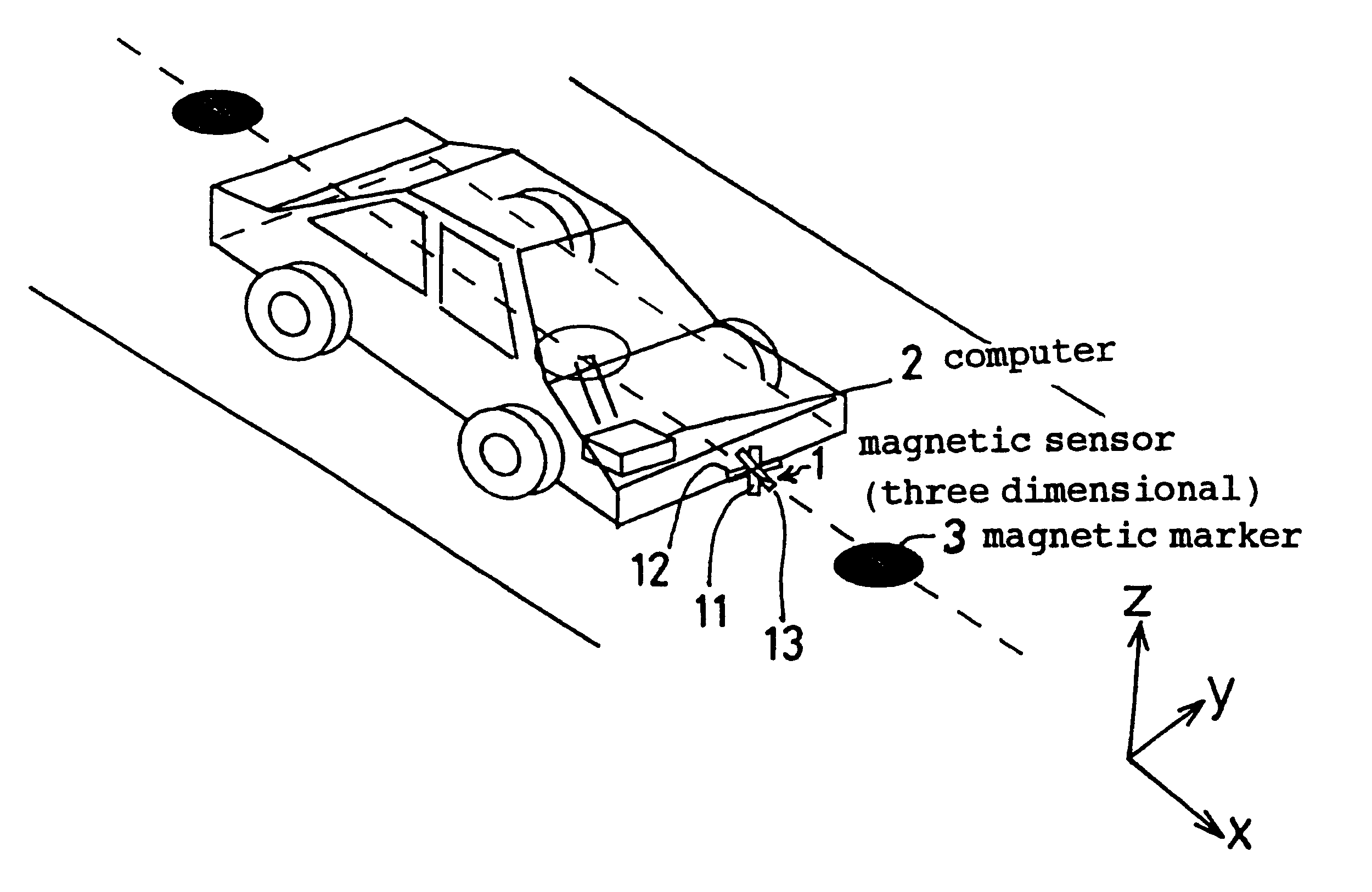
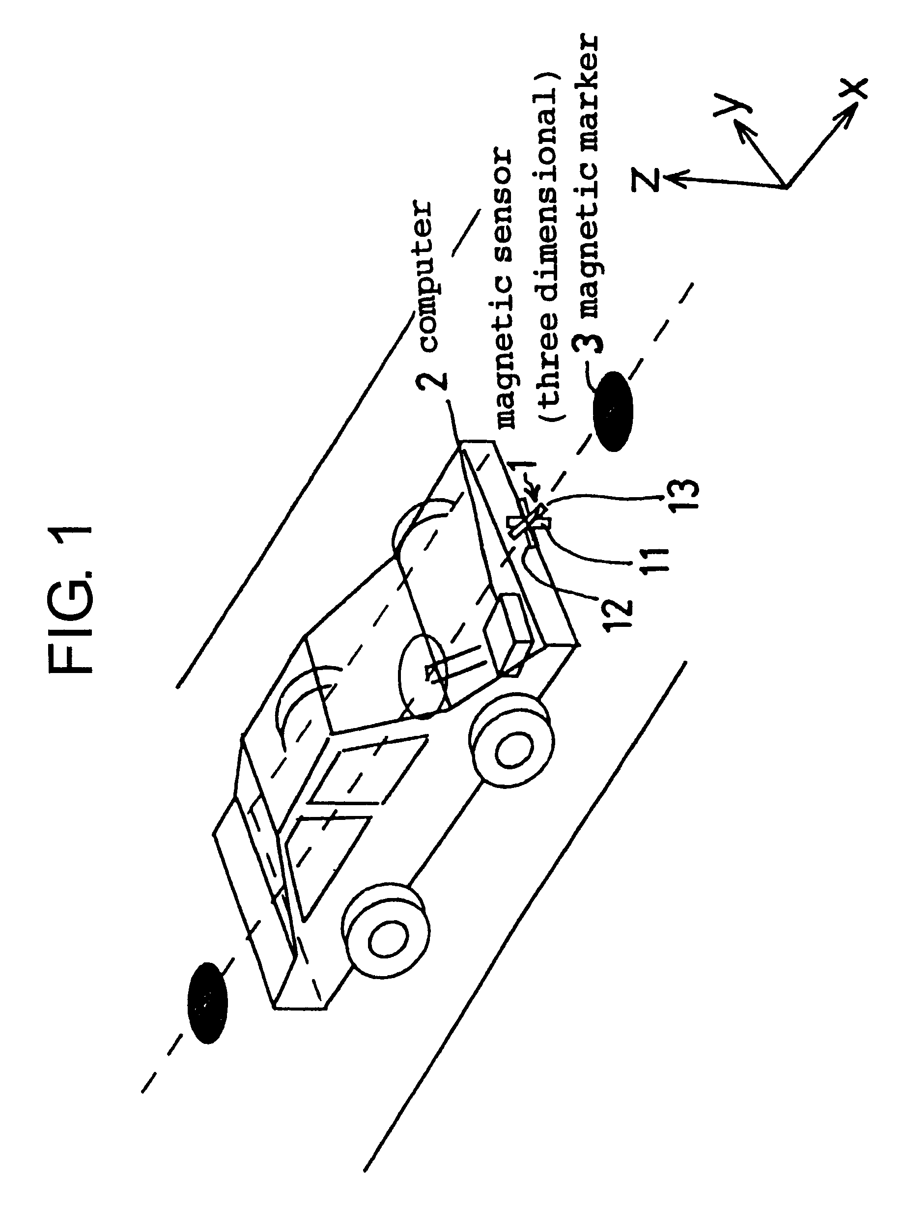
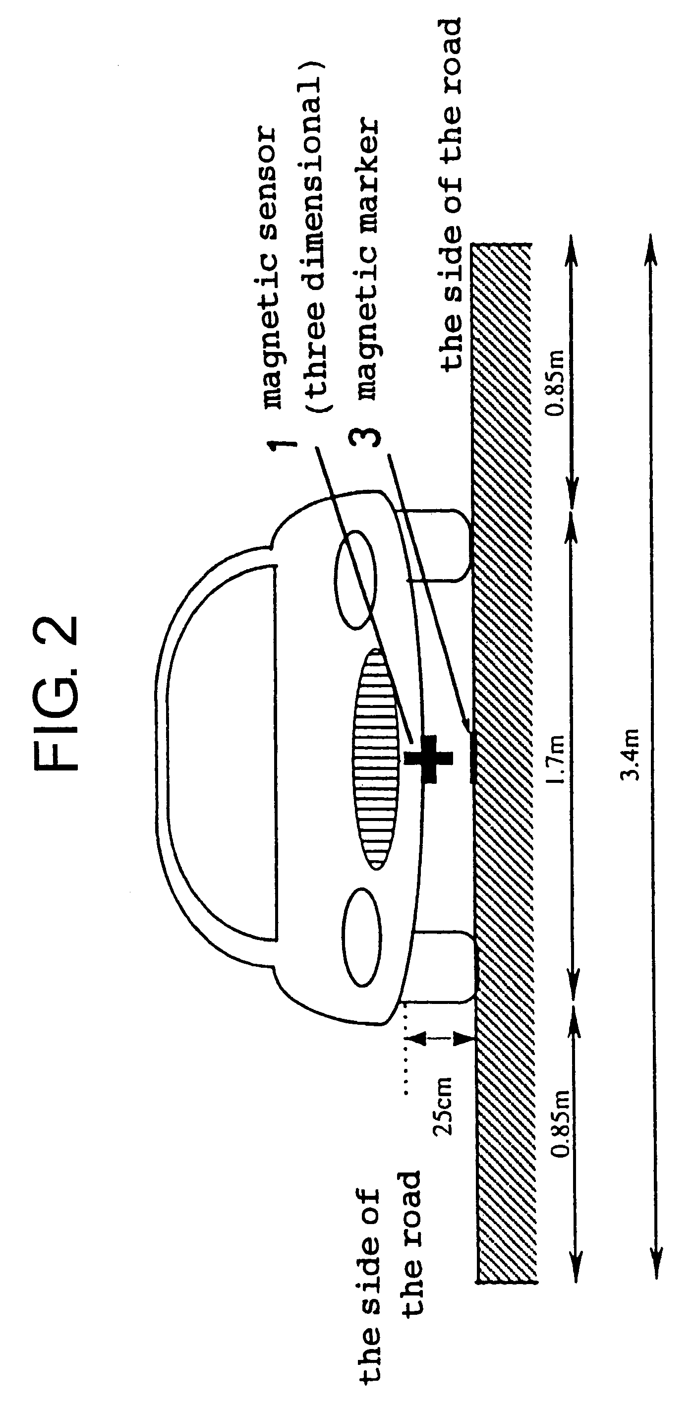
To solve this problem, the inventors found out a new method to enhance the ability of the sensor for keeping a position of a vehicle on the centerline and to extend the detectable range of the sensor for the lateral deviating distance from 25 cm to 1 m. The detectable range becomes 4 times larger. The method is characterized by detecting the longitudinal component of the magnetic field. The longitudinal component means along the lane. Moreover it is favorable to detect three components of the magnetic field. Three components are the longitudinal component, the vertical component and the transverse component. In this method, when the lateral deviating distance between the sensor and the marker becomes over 25 cm because of the misjudgment brought by external magnetic field, the system certainly and correctly guides the vehicle toward the centerline and recovers the vehicle at the center position of the lane.

Problems solved by technology

However, these methods, except magnetic methods, are difficult to apply to vehicles running on the road in bad weather (rain, snow, mist and so on).
The magnetic methods in which linearly arrayed sensors detect a magnetic line is usually adopted to an automatic driving system used in a plant, but it is difficult for arrayed sensors to apply to guiding vehicles on roads because of high speed and vertical oscillation.
But the problem remains that the vehicle deviates from the centerline over 25 cm and becomes out of control when the vehicle is running through bridges or tunnels because they are made of reinforced concrete that generate the magnetic field.
The magnetic markers are set along the centerline at the interval of 2 m. However there is the case that the vehicle deviates at distance of about 25 cm from the centerline while it goes about 1 m. In this undesirable case, the guiding system easily becomes out of control.
The range is insufficient.
It is necessary to detect the deviating distance from the centerline while a vehicle goes 2 m. And the above-mentioned system uses so complex method to calculate the position of vehicle that the system needs long time to identify the position of the vehicle.

Method used


Image

  • Magnetic apparatus for detecting position of vehicle
  • Magnetic apparatus for detecting position of vehicle
  • Magnetic apparatus for detecting position of vehicle

Examples


example

(2)

The second example to detect a lateral deviating distance is shown in the flow chart of FIG. 26.

This Example uses not Lx but Bxmax (Bx") in S132, differing from Example (1). As seen in FIG. 25 that shows experimental data, if a lateral deviating distance is longer than 500 mm, the affect of the height of a magnetic sensor 1 is negligible and there is a nearly linear relation between Bxmax and a lateral deviating distance. Thus in the case that a lateral deviating distance is longer than 500 mm, a lateral deviating distance is easily estimated from a prerecorded formula between Bxmax and a deviating distance (FIG. 25) without correcting a height of a magnetic sensor 1. The experiment is made in same condition to that of FIG. 24.


PUM


Abstract

A magnetic apparatus for detecting a position of a vehicle, capable of detecting a lateral deviating distance of a vehicle over a lateral deviation width with a high accuracy and at a high speed, wherein a magnetic field component in the direction of advance of the vehicle is detected; or more preferably a three dimensional magnetic sensor (1), which comprises a magnetic sensor element for the direction of advance of the vehicle, and magnetic sensor elements for two directions crossing the first-mentioned direction and provided additionally, is used, whereby it becomes possible to heighten a center retaining capability of the vehicle, widen a lateral deviating distance detecting range around four times from around 25 cm to around 1 m, and detect a magnetic marker (3) reliably even when disturbance magnetic field exerts influence upon this detection operation to thereby start center side guidance reliably.

Description

The present invention relates to a magnetic apparatus for detecting a position of a vehicle that calculates a lateral deviating distance of a vehicle from the centerline on the road by detecting a magnetic field generated from magnetic markers located on the centerline of the road.An automatic driving system has been researched by various approaches. The principles for these approaches are to detect a cable with current by a pickup coil, to analyze a figure by camera, to use radiowaves, to use an ultrasonic device, to detect magnetic tape by a magnetic sensor and so on. However, these methods, except magnetic methods, are difficult to apply to vehicles running on the road in bad weather (rain, snow, mist and so on). The magnetic methods in which linearly arrayed sensors detect a magnetic line is usually adopted to an automatic driving system used in a plant, but it is difficult for arrayed sensors to apply to guiding vehicles on roads because of high speed and vertical oscillation.U...

Claims


Application Information

Patent Timeline
IPC IPC(8): G01C21/26
CPCG01C21/26G08G1/09623G08G1/167B62D15/025
Inventor HONKURA, YOSHINOBUFUJII, HIDEKIWATARAI, AKIEIJI, KAKO
Owner AICHI STEEL
Learn More