Flotation apparatus for clarifying produced water

a technology of flotation apparatus and produced water, which is applied in the field of flotation, can solve the problems of difficult, if not impossible, to monitor the amount of oil and other contaminants flowing out the open bottom into the sea, and the flow rate is relatively low, so as to achieve complete and faster separation of oils

Inactive Publication Date: 2002-01-08
SIEMENS ENERGY INC
View PDF43 Cites 65 Cited by
  • Summary
  • Abstract
  • Description
  • Claims
  • Application Information

AI Technical Summary

Benefits of technology

It is a further object of the present invention to provide a gas flotation apparatus and process which obtains more complete and faster separation of oils, solids, and other insoluble and/or suspended substances from produced water without turbulence and back-mixing.
Another object of the present invention is to provide a gas flotation apparatus and process which can separate dilute concentrations of oils, solids, and other insoluble and/or susp

Problems solved by technology

A major problem faced in these industrial operations is the economic separation of the oil, suspended solids, and/or other insoluble substances from the water so that the water can be reused or discharged into the environment.
This separation problem is especially prevalent in the offshore production of crude petroleum and natural gas, where many oil and gas wells produce a certain amount of water or brine ("produced water") in conjunction with the oil and gas.
Two major limitations of skim piles are that they can only handle relatively low flow rates and they are generally ineffective at removing finely suspended solids or insoluble liquid droplets.
Furthermore, it is difficult, if not impossible, to monitor the amount of oil and other contaminants flowing out the open bottom into the sea.
For these and other reasons, skim piles are no longer the preferred method for separating oil from produced water.
A drawback is that the filter elements typically have a complex internal design and tend to get saturated with oil and plugged with suspended contaminants, necessitating frequent replacement or cl

Method used


Image

  • Flotation apparatus for clarifying produced water
  • Flotation apparatus for clarifying produced water
  • Flotation apparatus for clarifying produced water

Examples


Embodiment Construction

While the present invention will be described with reference to preferred embodiments, it will be understood by those skilled in the art that various changes may be made and equivalents may be substituted for elements thereof without departing from the scope of the invention. In addition, many modifications may be made to adapt a particular situation or material to the teachings of the invention without departing from the essential scope thereof. Therefore, it is intended that the present invention not be limited to the particular embodiments disclosed as the best mode contemplated for carrying out this invention, but that the invention will include all embodiments (and legal equivalents thereof) failing within the scope of the appended claims.

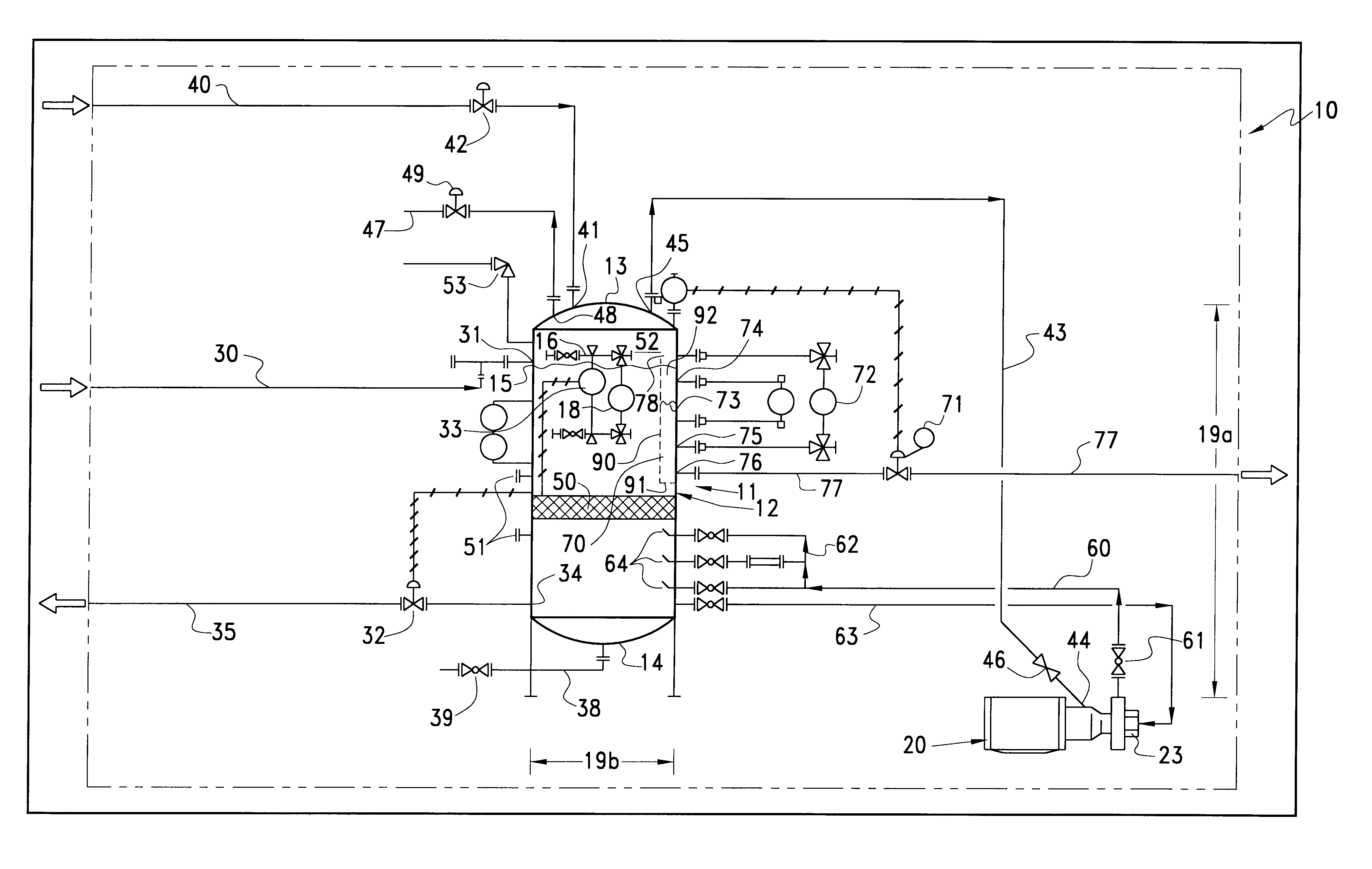
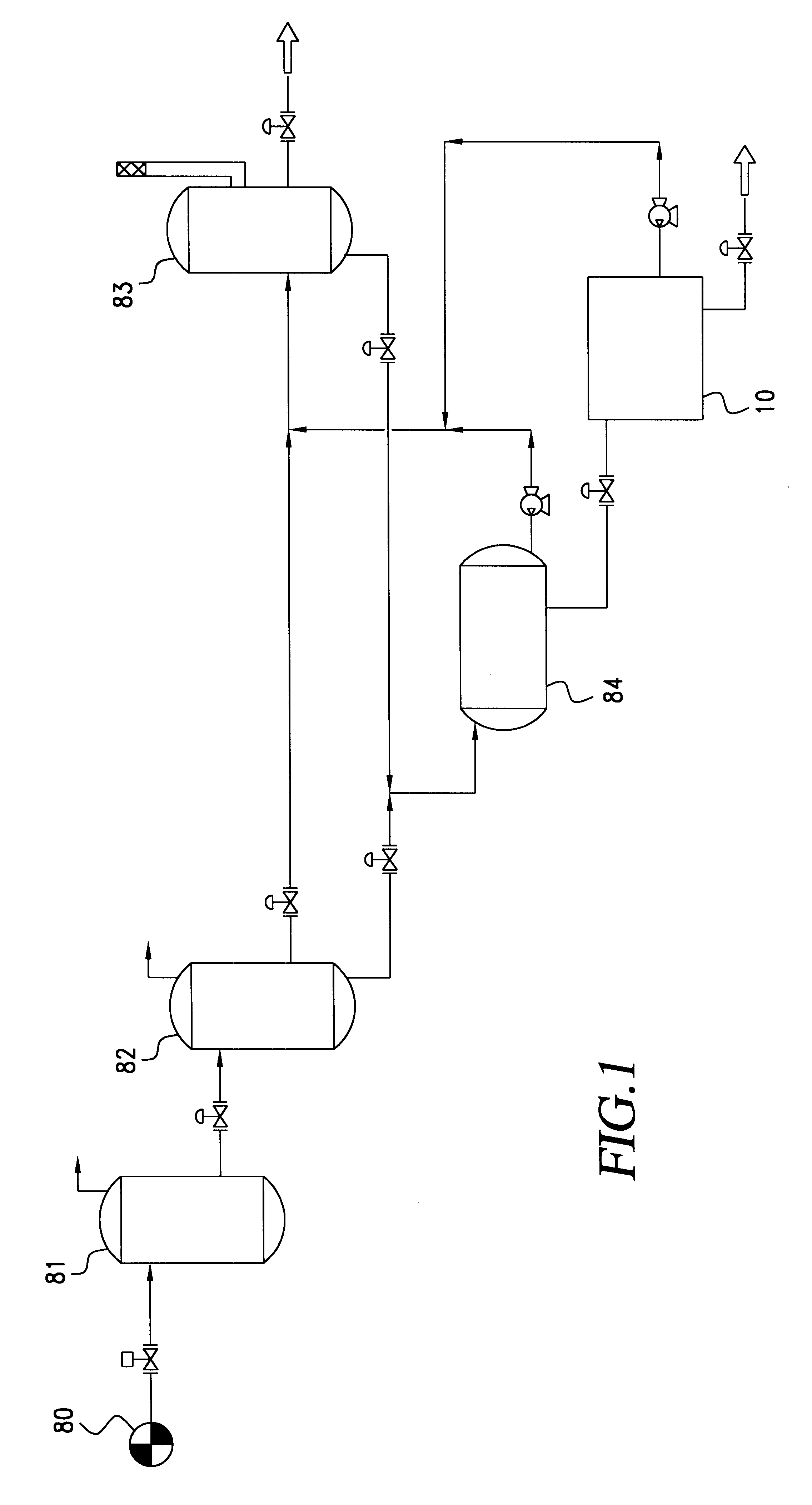
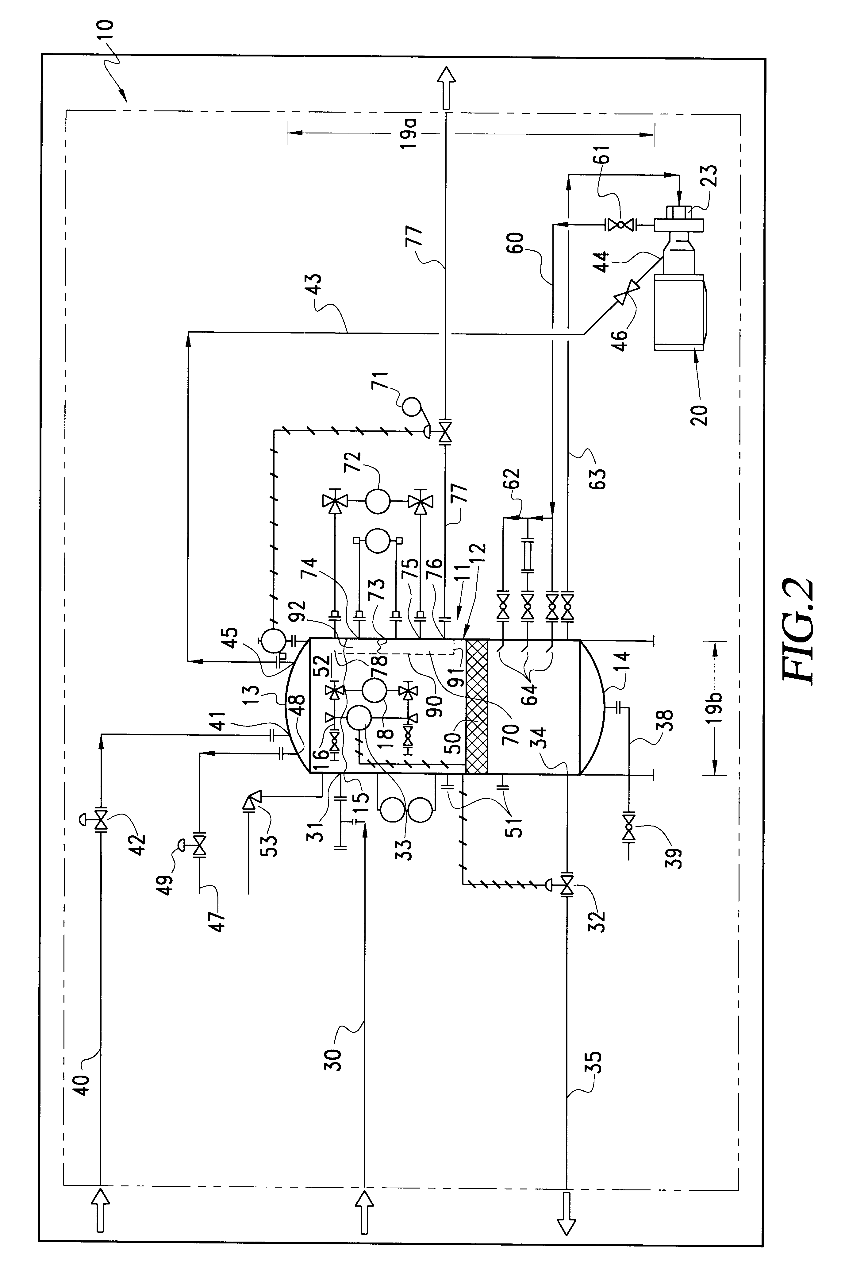
The gas flotation apparatus and process of the present invention can, in general, be used to remove oils, solids, and other insoluble and / or suspended substances (sometimes collectively referred to as "oil and other contaminants") from a liqui...


PUM

PropertyMeasurementUnit
Pressureaaaaaaaaaa
Flow rateaaaaaaaaaa
Levelaaaaaaaaaa

Abstract

A dissolved gas flotation apparatus and process for removing oils and other contaminants from produced water generated in the production of crude petroleum and natural gas. The invention is particularly designed for offshore applications, where space is limited and natural gas is readily available. The invention includes a vessel for receiving and maintaining a liquid level therein and a circulating pump for introducing tiny flotation gas bubbles into the vessel. Natural gas is used as a blanket gas for the vessel and as a source of gas fed into the pump, wherein the gas is mixed with the pumped liquid. The liquid/gas mixture is transferred into the vessel, wherein the gas releases from the liquid, thereby forming tiny, finely dispersed gas bubbles. The tiny gas bubbles rise vertically through the vessel and attach themselves to the oil and other contaminants suspended in the liquid and buoyantly transport the oil and other contaminants to the top of the vessel, where the gas is released and either recycled back to the recirculating pump or transferred out of the vessel for further processing, and the oil and other contaminants are collected in a reservoir for recovery. The clarified water is removed from the vessel through a liquid outlet line located near the bottom of the vessel.

Description

1. Field of the InventionThe present invention relates generally to an apparatus and a process for the removal of insoluble substances from a liquid. More particularly, the present invention relates to a flotation apparatus and process for removing oils, solids, and other insoluble and / or suspended substances from produced water which is typically generated during the production of crude petroleum and natural gas.2. Description of Related ArtWater contaminated with small amounts of oil, suspended solids, and / or other insoluble substances is a byproduct of many industrial operations such as, for example, the production and refining of crude petroleum and natural gas; the manufacturing of chemicals, paint, textiles, paper and pulp; the generation of electricity; and the processing of metals, food and beverages. A major problem faced in these industrial operations is the economic separation of the oil, suspended solids, and / or other insoluble substances from the water so that the water...

Claims


Application Information

Patent Timeline
IPC IPC(8): B01D17/00B03D1/14C02F1/24
CPCB01D17/00C02F1/24B03D1/1431B03D1/16B03D1/028B01D17/0205B01D17/12
Inventor BROUSSARD, SR., PAUL C.BROUSSARD, JR., PAUL C.
Owner SIEMENS ENERGY INC
Why Eureka
Try Eureka