Thermal silhouette target and zeroing technique

a silhouette target and target technology, applied in the field of thermal silhouette targets, can solve the problems of hole disappearance, soldier's inability to spot targets, and no specific technique and target base has been established

Inactive Publication Date: 2002-01-08
UNITED STATES OF AMERICA THE AS REPRESENTED BY THE SEC OF THE ARMY
View PDF1 Cites 17 Cited by
  • Summary
  • Abstract
  • Description
  • Claims
  • Application Information

AI Technical Summary

Problems solved by technology

If a hole is used, the E-Type target will eventually heat up the paper and cause the hole to disappear a seen by the TIS because of an eventual lack of temperature difference.
If the foil sticker is used, the precise angle the target presented to the soldier becomes critical, since if the target is not perfectly aligned, the soldier will not be able to spot the target.
While the prior art has reported using thermal silhouette targets none have established a basis for a specific technique and target that is dedicated to the task of resolving the particular problem at hand.

Method used


Image

  • Thermal silhouette target and zeroing technique
  • Thermal silhouette target and zeroing technique
  • Thermal silhouette target and zeroing technique

Examples


Embodiment Construction

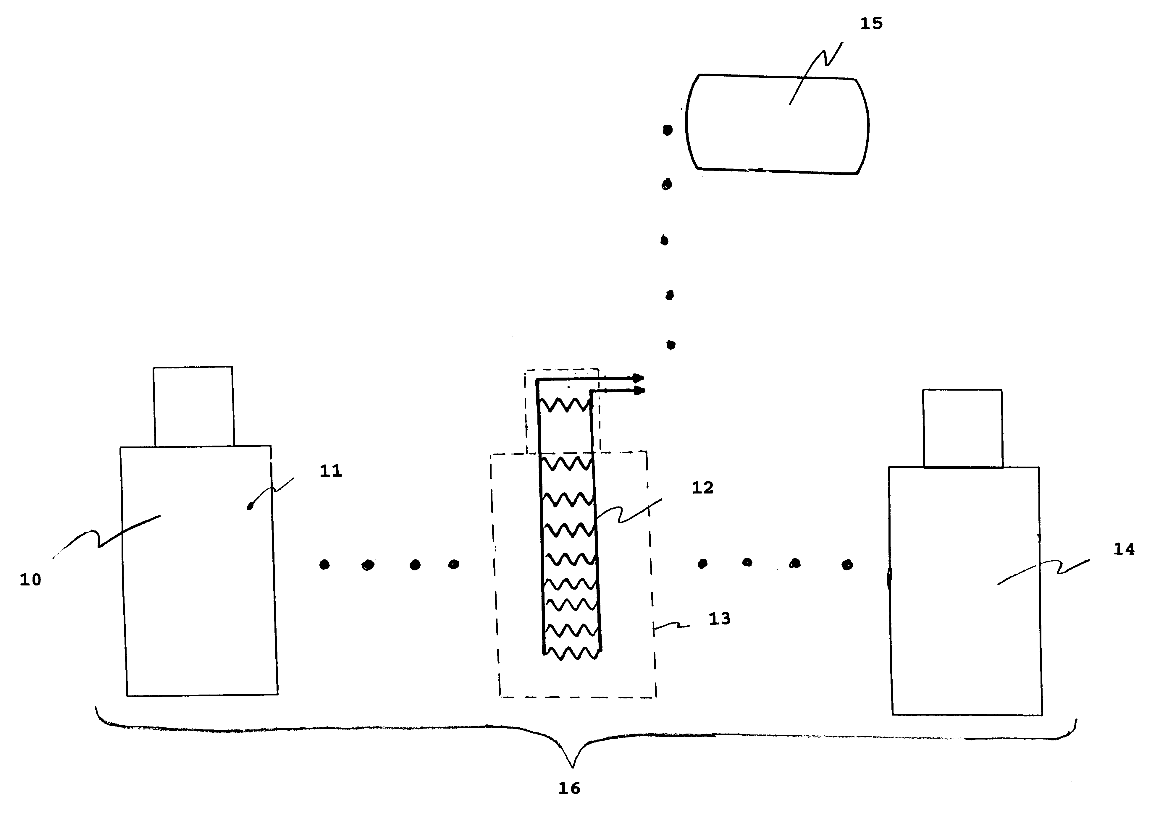
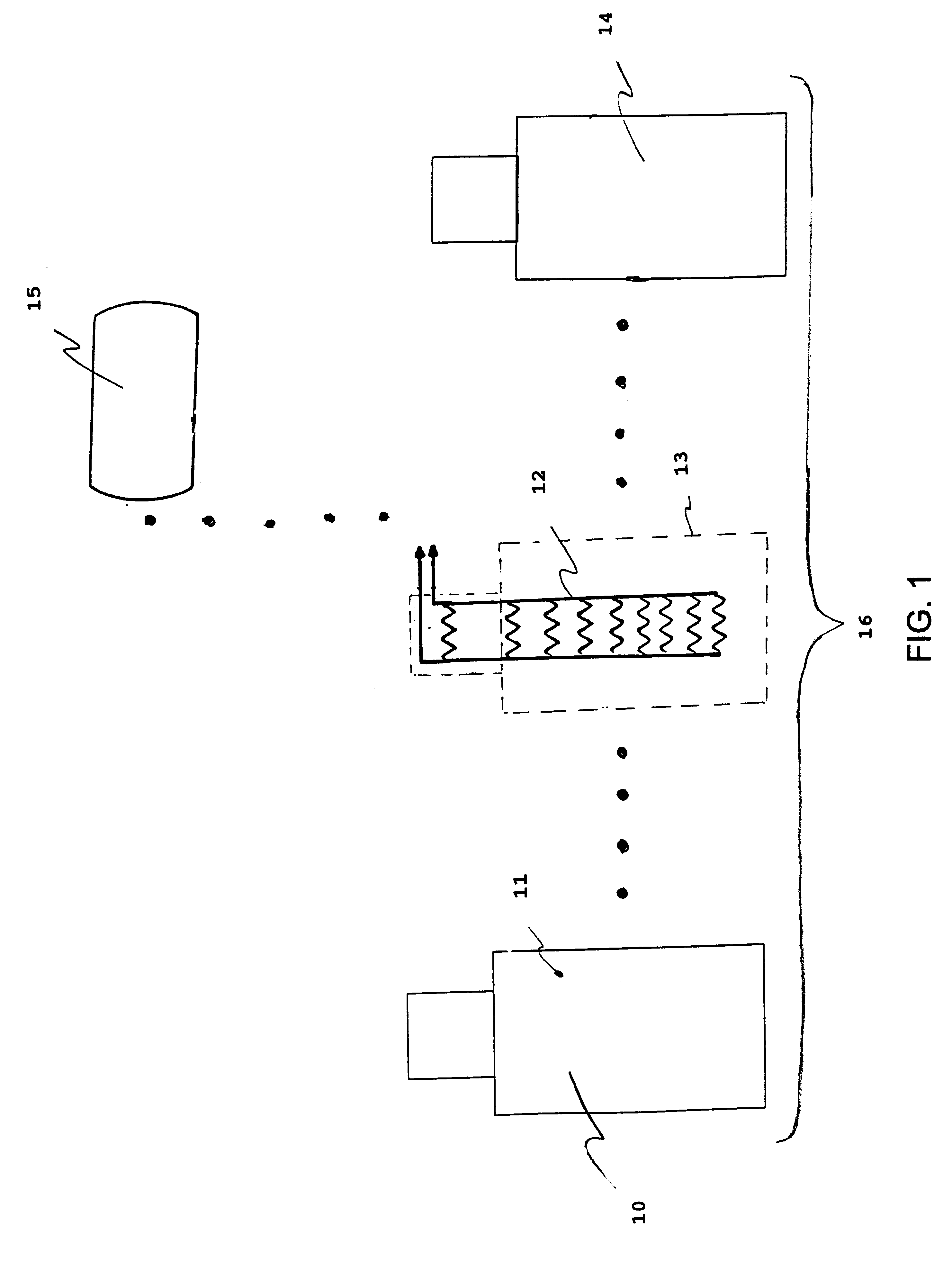
Referring now to the drawings, and more particularly to FIG. 1, there is shown an exploded front view of the elements of the thermal silhouette target device of the present invention with copper foil layer 10 with a silhouette shape. It is understood that the invention is not limited to a particular silhouette as the zeroing target. Front surface 11 of copper foil layer 10 is painted with high emissivity ultra-flat paint. Heating coil 12 is a shellac insulated copper wire that is attached to the back side of copper foil layer 10 in a general position relative to shape outline 13 as shown in FIG. 1. Layer 14 is a synthetic polymer film, such as MYLAR or acetate that is attached over heating coil 12. Zeroing target 16 is removably attached to a zeroing target background and voltage source 15 is removably attached to heating coil 12 prior to the zeroing process. Voltage source in the preferred embodiment is a 1.5 V dc standard battery, which may be external or attached on the back of t...


PUM


Abstract

A thermal silhouette target including a high emissivity surface, a conductive layer, a heating coil, an insulative layer and a direct voltage source. A thermal zeroing silhouette target device further includes a mask with a zeroing grid and a pair of contacts for electrical connection to a direct voltage current source.

Description

1. Field of the InventionThe present invention generally relates to thermal silhouette targets and more specifically, to a multi-layer electrically heated thermal silhouette target for 25 meter zeroing of a weapon mounted Thermal Imaging Sensor.2. Description of Prior ArtThermal imaging Sensors (TIS) must be zeroed before being used on a weapon. The current method to zero a TIS utilizes a large heated E-Type silhouette target along with attaching a modified non-thermal 25 meter zeroing target. The target provides temperature difference by either having a hole cut into it (air temperature difference), or pasting a foil sticker (reflective temperature difference) on it. The heated E-Type silhouette must use a 110 VAC or a large 12 / 24 Vdc power source.If a hole is used, the E-Type target will eventually heat up the paper and cause the hole to disappear a seen by the TIS because of an eventual lack of temperature difference. If the foil sticker is used, the precise angle the target pres...

Claims


Application Information

Patent Timeline
Patent Type & Authority Patents(United States)
IPC IPC(8): H01L27/00F41H3/00
CPCF41H3/00F41J2/02
Inventor MIGLIORINI, ROBERT L.
Owner UNITED STATES OF AMERICA THE AS REPRESENTED BY THE SEC OF THE ARMY
Why Eureka
Try Eureka