
Agitating member, developing apparatus and process cartridge

a technology of developing apparatus and agitating member, which is applied in the direction of electrographic process apparatus, instruments, developers, etc., can solve the problems of inability to cohere toner, deterioration speed by friction between toner grains becomes higher, and toner humidity absorbance becomes greater. , to achieve the effect of sufficient agitation for

Inactive Publication Date: 2002-01-08
CANON KK
View PDF11 Cites 84 Cited by
  • Summary
  • Abstract
  • Description
  • Claims
  • Application Information

AI Technical Summary

Benefits of technology

It is a primary object of the present invention to provide an agitating member that can obtain a sufficient agitating force even in a small space.
It is another object of the present invention to provide agitating means and a developing apparatus that enable a toner contained in a developer container to be utilized without waste as far as possible.
It is another object of the present invention to provide a developing apparatus in which the deterioration of a toner can be prevented and even under a high-temperature, high-humidity environment, the scattering of the toner is small and a high quality of image can be obtained and further, uniform density can be obtained in an image area.
It is another object of the present invention to provide a process cartridge in which the deterioration of a toner can be prevented and even under a high-temperature, high-humidity environment, the scattering of the toner is small and a high quality of image can be obtained, and a stable density can be obtained during the service life of the cartridge, and to provide an electrophotographic image forming apparatus provided with such a process cartridge.

Problems solved by technology

However, by the toner being fine-grained, the surface area per unit volume of toner becomes larger and therefore, the deterioration speed by the friction between toner grains becomes higher.
Also, under a high-humidity environment, the humidity-absorbing amount of the toner tends to become greater, and the toner becomes liable to cohere.

Method used


Image

  • Agitating member, developing apparatus and process cartridge
  • Agitating member, developing apparatus and process cartridge
  • Agitating member, developing apparatus and process cartridge

Examples


first embodiment

[First Embodiment]

An embodiment of the developing apparatus constructed in accordance with the present invention will first be described with reference to FIG. 1.

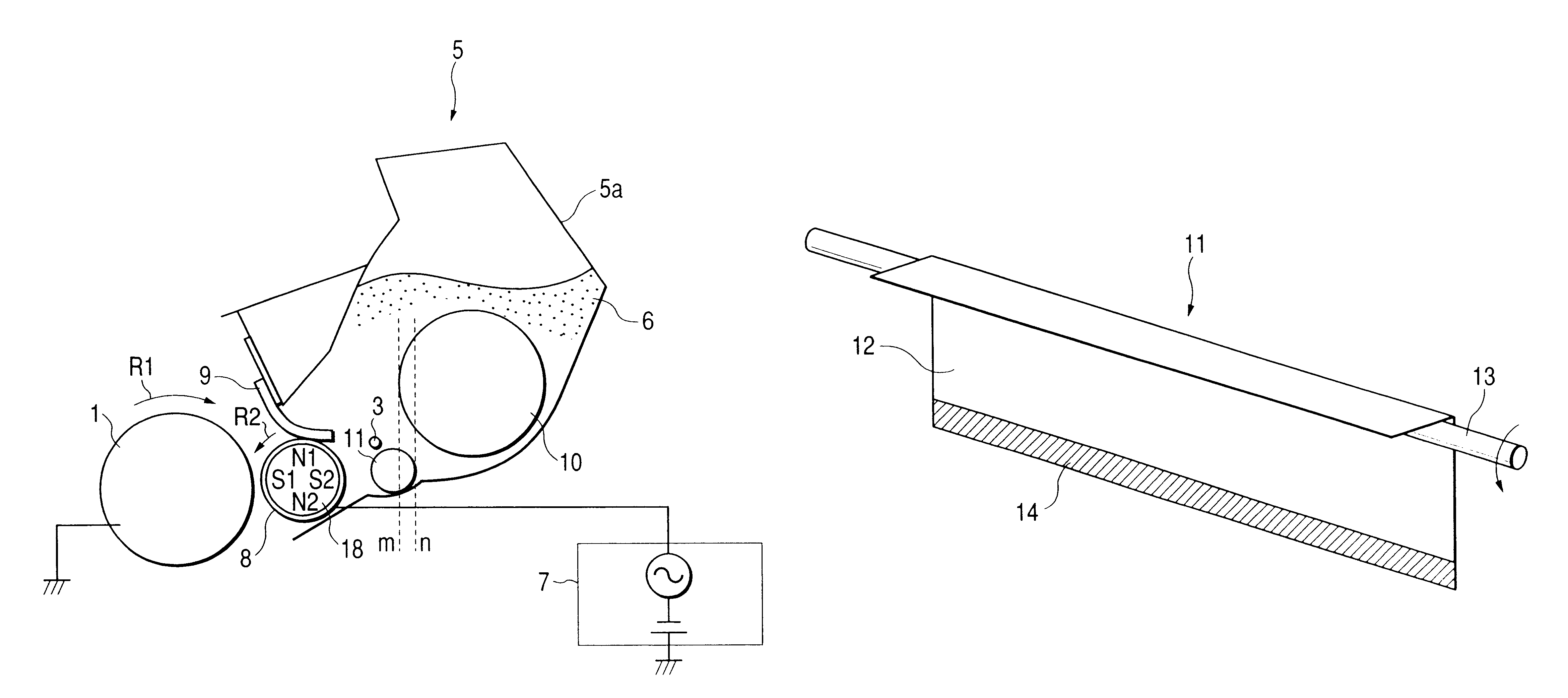
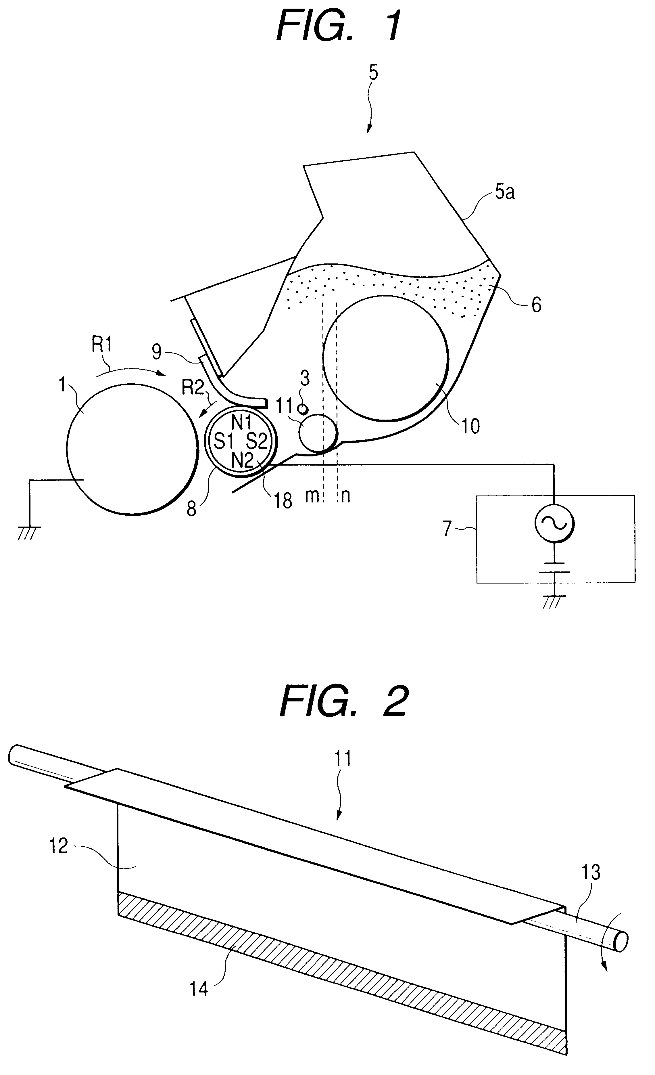
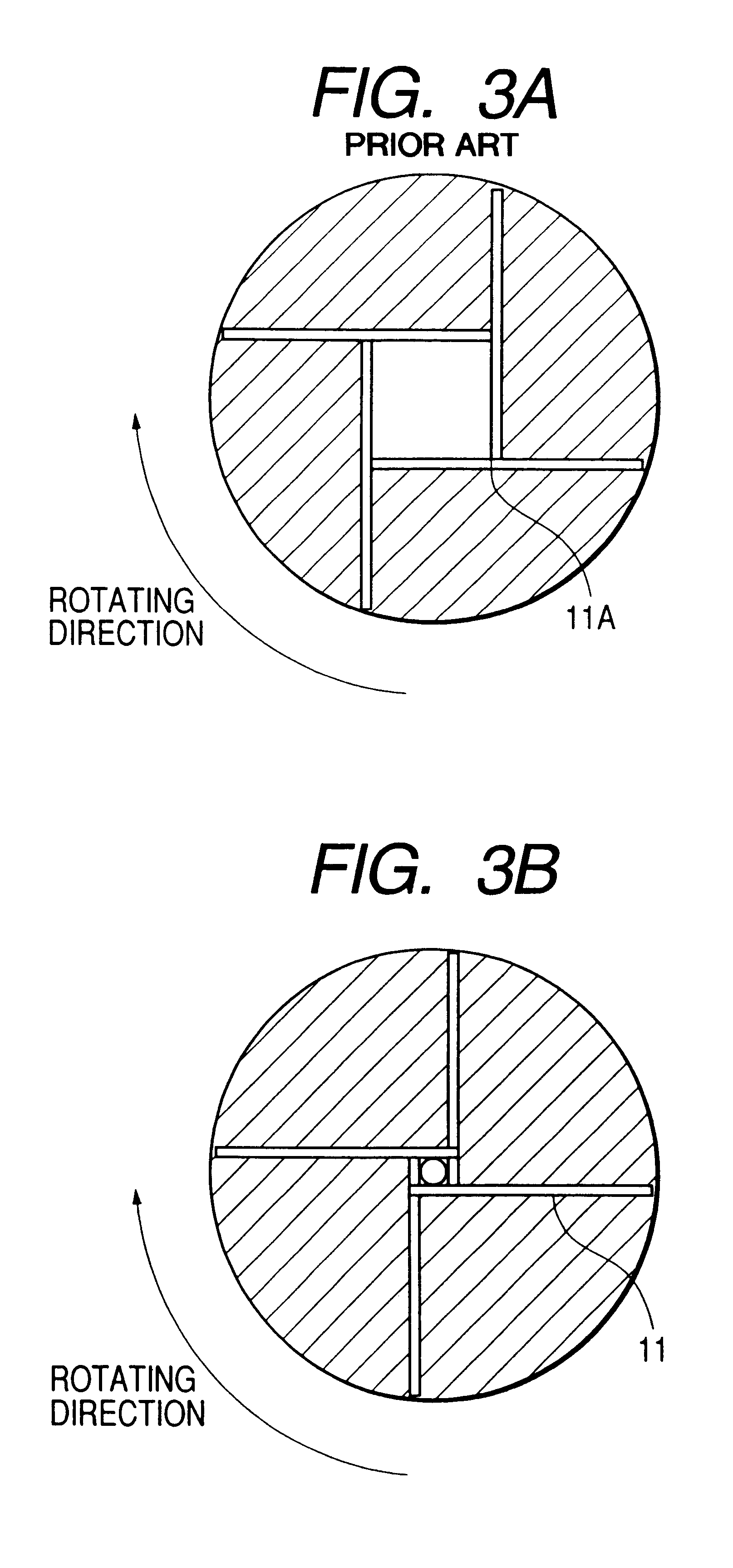
The developing apparatus 5 according to the present embodiment has a developer container 5a storing a toner (developer) 6 therein at the right in FIG. 1, and in the developer container 5a, there are installed first and second agitating means 10 and 11 for carrying the toner 6 to a developing roller 8 as a developer bearing member opposed to a photosensitive drum 1, which is an electrophotographic photosensitive member laterally provided in an opening portion formed at the left of the developer container 5a and rotated in the direction of arrow R1.

Also, a developing blade 9, as a developer regulating member for regulating the amount of the toner 6 borne on the developing roller 8, bears on the developing roller 8 in a direction counter to the rotating direction R2 of the developing roller 8.

The first agitating means (agitati...

second embodiment

[Second Embodiment]

A second embodiment is a further development of the agitating means 11 according to the first embodiment.

The shape of the metal rod 13, which is a support shaft, is made concave, and the adhesive securing thereof to the L-shaped metal plate 12 is effected in a plane and the fixing thereof is stabilized.

Also, in the first embodiment, as the construction for transmitting the drive from the gear 15 to the first agitating means 10, a portion of the end of the gear 15 is adapted to catch on the L-shaped metal plate 12 and therefore, it is necessary to select a material of such strength that the portion of the gear can stand the torque during driving. So, in the present embodiment, the construction of that portion that transmits the drive has been developed so that the gear can sufficiently stand the torque of driving.

The agitating means 11 according to the present embodiment is shown in FIG. 8.

In the present embodiment, as shown in FIG. 8, the shape of a metal rod 13, ...

third embodiment

[Third Embodiment]

A third embodiment of the present invention will now be described with reference to FIG. 11. This embodiment is a process cartridge provided in the developing apparatus of the present invention.

In FIG. 11, the process cartridge C according to the present embodiment comprises a cylindrical photosensitive drum 1 which is an electrophotographic photosensitive member, a charging device 2 for charging the surface of the photosensitive drum 1, a developing apparatus 5 for visualizing a latent image on the surface of the photosensitive drum 1, and a cleaning device 17 for removing the toner 6 untransferred and remaining on the photosensitive drum 1 after transfer, these being made integral with one another, and is detachably attached to the main body of the image forming apparatus.

The process cartridge C according to the present embodiment is provided with the second agitating means 11 according to the second embodiment.

The process cartridge has become maintenance-free an...


PUM


Abstract

An agitating member for agitating a developer includes a metal shaft, a plate member joined to the metal shaft, and a sheet member joined to the plate member, the sheet member being free to curve. A developing apparatus includes a developer bearing member bearing a developer thereon, a developer container containing the developer therein, and the above-described agitating member provided in the developer container for agitating the developer and supplying it to the developer bearing member. A process cartridge detachably attachable to the main body of an image forming apparatus, includes an electrophotographic photosensitive member and the above-described developing apparatus.

Description

BACKGROUND OF THE INVENTION1. Field of the InventionThis invention relates to a process cartridge and a developing apparatus mounted to an image forming apparatus of the electrophotographic type such as a copier, a page printer or a facsimile apparatus, and further to agitating means mounted to the process cartridge and the developing apparatus.2. Related Background ArtAn example of the developing apparatus is shown in FIG. 15 of the accompanying drawings.This developing apparatus 105 is provided with a developer container 105a for effecting the storage and custody of a toner (developer) 106, and a developing roller 108 which is a developer bearing member. A developing blade 109, which is a developer regulating member, bears on the developing roller 108, and serves to regulate the amount of the toner 106 on the developing roller 108 and charge the toner 106.Also, there are often provided agitating means 110 and 111 for loosening the toner 106 in the developer container 105a and feed...

Claims


Application Information

Patent Timeline
IPC IPC(8): G03G15/08G03G9/08
CPCG03G15/0822G03G21/1814G03G2221/183
Inventor INAMI, SATORUKATO, JUNICHIYOSHIDA, MASAHIRONAKAZONO, YUSUKESHINOHARA, SEIICHI
Owner CANON KK
Learn More