Card connector mounting structure

a card connector and mounting structure technology, applied in the direction of coupling device connection, electrical apparatus casing/cabinet/drawer, instruments, etc., can solve the problems of slipping of the contact position, affecting the performance and affecting the operation of the card insert/withdrawing operation

Inactive Publication Date: 2002-01-29
YAMAICHI ELECTRONICS
View PDF11 Cites 33 Cited by
  • Summary
  • Abstract
  • Description
  • Claims
  • Application Information

AI Technical Summary

Problems solved by technology

In any one of the above mentioned conventional devices, it is essentially required to employ an additional pressing closure member solely for the purpose of providing pressure contact, which naturally ...

Method used


Image

  • Card connector mounting structure
  • Card connector mounting structure
  • Card connector mounting structure

Examples


Embodiment Construction

Embodiments of the present invention will now be described with reference to FIGS. 1 to 9.

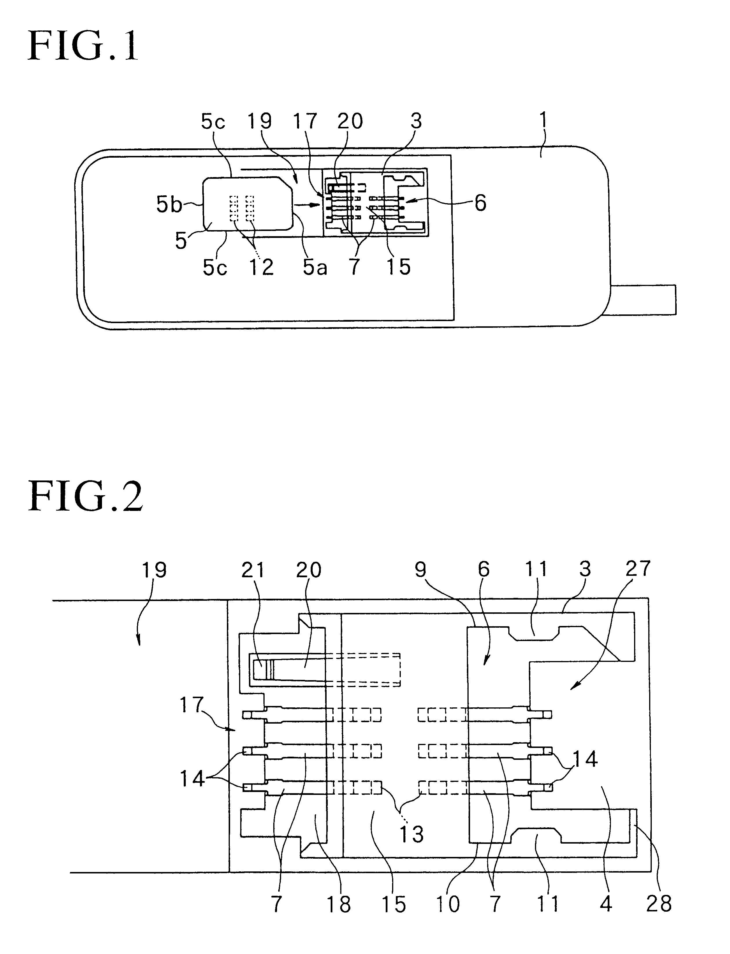
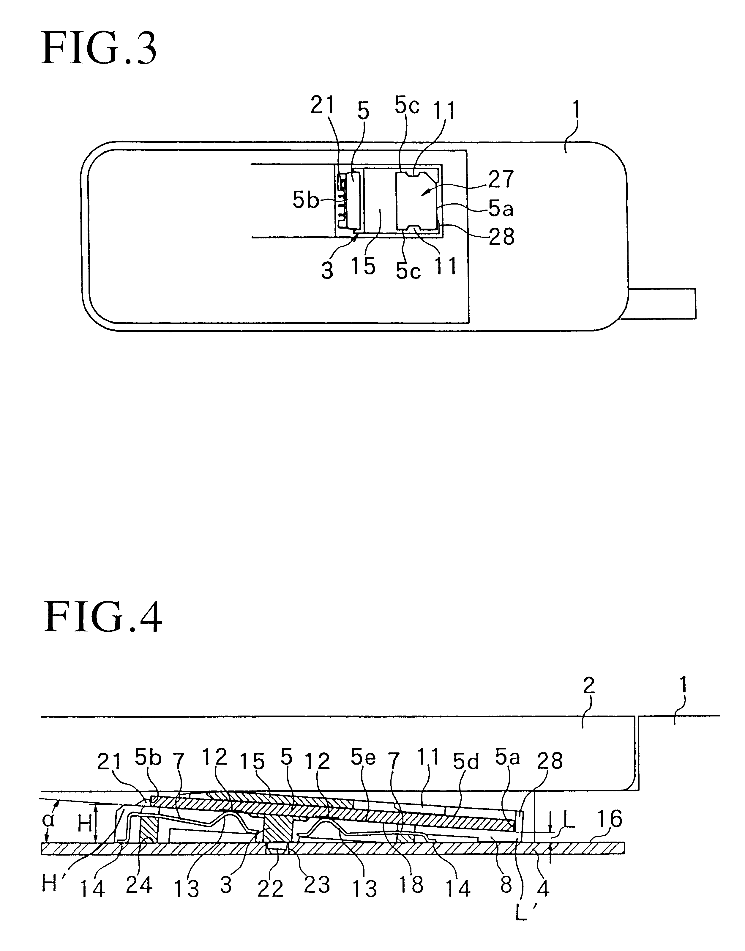
FIGS. 1 to 4 show a portable telephone as a representative example of an electronic device 1. This portable telephone includes a closure member 2 which also serves as a battery case. When the closure member 2 is opened, a card connector body 3 and a part of a wiring circuit board 4 on which the connector is surface mounted are exposed within an opening plane as shown in FIG. 3.

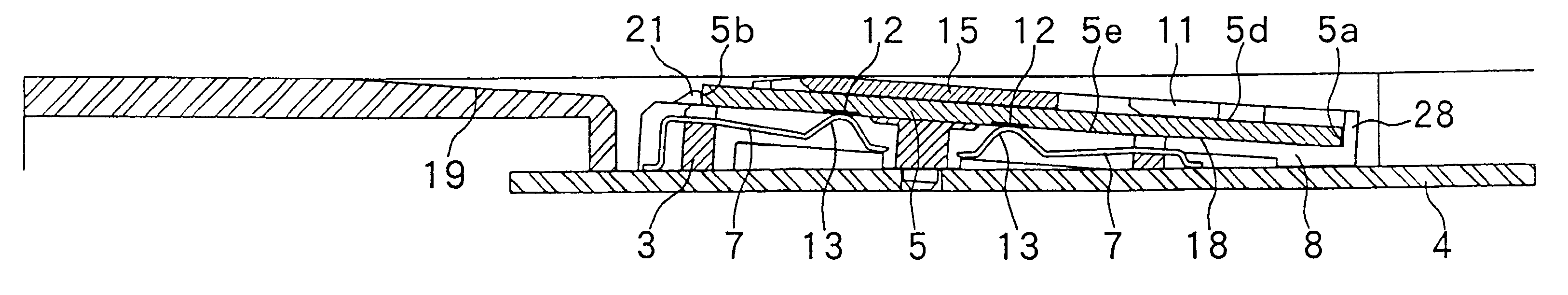
An IC card 5 is inserted into a card insertion space 6 which is defined within the exposed card connector body 3 and pressure contacted with contacts 7 which are arranged with respect to the card insertion space 6 as shown in FIGS. 3 and 4.

The battery case in the form of the closure member 2 of the card insertion space 6 is closed to hide the connector body 3 into which the IC card 5 has been inserted.

The connector body 3 includes a first and a second side wall 9, 10 extending in opposing relation to a right and a left si...


PUM


Abstract

A mounting structure of a card connector includes a connector body surface mounted on a wiring circuit board. An IC card can be withdrawably inserted into the connector body so that the IC card can be connected to the wiring circuit board through the connector body. The connector body includes a card insertion space which is disposed at an angle of inclination with respect to an upper surface of the wiring circuit board. A card inlet/outlet port is formed at an upper inclination end of the card insertion space such that the IC card inserted into the card insertion space through the card inlet/outlet port is retained for connection at an angle of inclination.

Description

1. Field of the InventionThis invention relates to an IC card connector used for such electronic devices as telephones, cash dispensers, personal computers, cameras and the like.2. Related ArtBefore describing the art related to the present invention, it should be noted that the term "IC card" herein used refers to a card which contains a write / read memory or both a memory and a CPU and which can be put into a purse, a handbag, a pocket or the like for carriage. The IC card of this type is inserted for use in the above-mentioned electronic device. A conventional card connector mounted on a wiring circuit board is built in a given electronic device and an IC card is inserted into and withdrawn from the card connector in its posture held in parallel relation to a wiring circuit board into a card insertion space of the card connector through a card inlet / outlet port formed in an external wall of the electronic device. In the conventional card connector, it is essentially required to fo...

Claims


Application Information

Patent Timeline
IPC IPC(8): G06K7/00H01R13/24H01R13/22H01R12/00H01R12/71G06K17/00H01R24/00
CPCG06K7/0021H01R13/2442G06K7/003Y10S439/954
Inventor TAKEYAMA, TETSUOIGARASHI, MINORU
Owner YAMAICHI ELECTRONICS
Why Eureka
Try Eureka