Temperature and humidity sensor assembly

a temperature and humidity sensor and sensor assembly technology, which is applied in the direction of heating types, instruments, domestic cooling devices, etc., can solve the problem that the current electronic air temperature controller (eatc) does not have the capability to determine if the windshield is damaged

Inactive Publication Date: 2002-02-19
VISTEON GLOBAL TECH INC
View PDF13 Cites 33 Cited by
  • Summary
  • Abstract
  • Description
  • Claims
  • Application Information

AI Technical Summary

Problems solved by technology

Current electronic air temperature controllers (EATCs) do not have the capability to determine if the windshield is fogging or about to fog.

Method used


Image

  • Temperature and humidity sensor assembly
  • Temperature and humidity sensor assembly
  • Temperature and humidity sensor assembly

Examples


Embodiment Construction

)

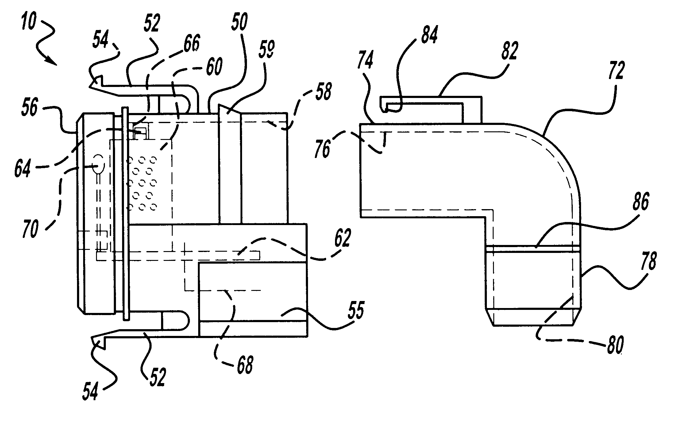
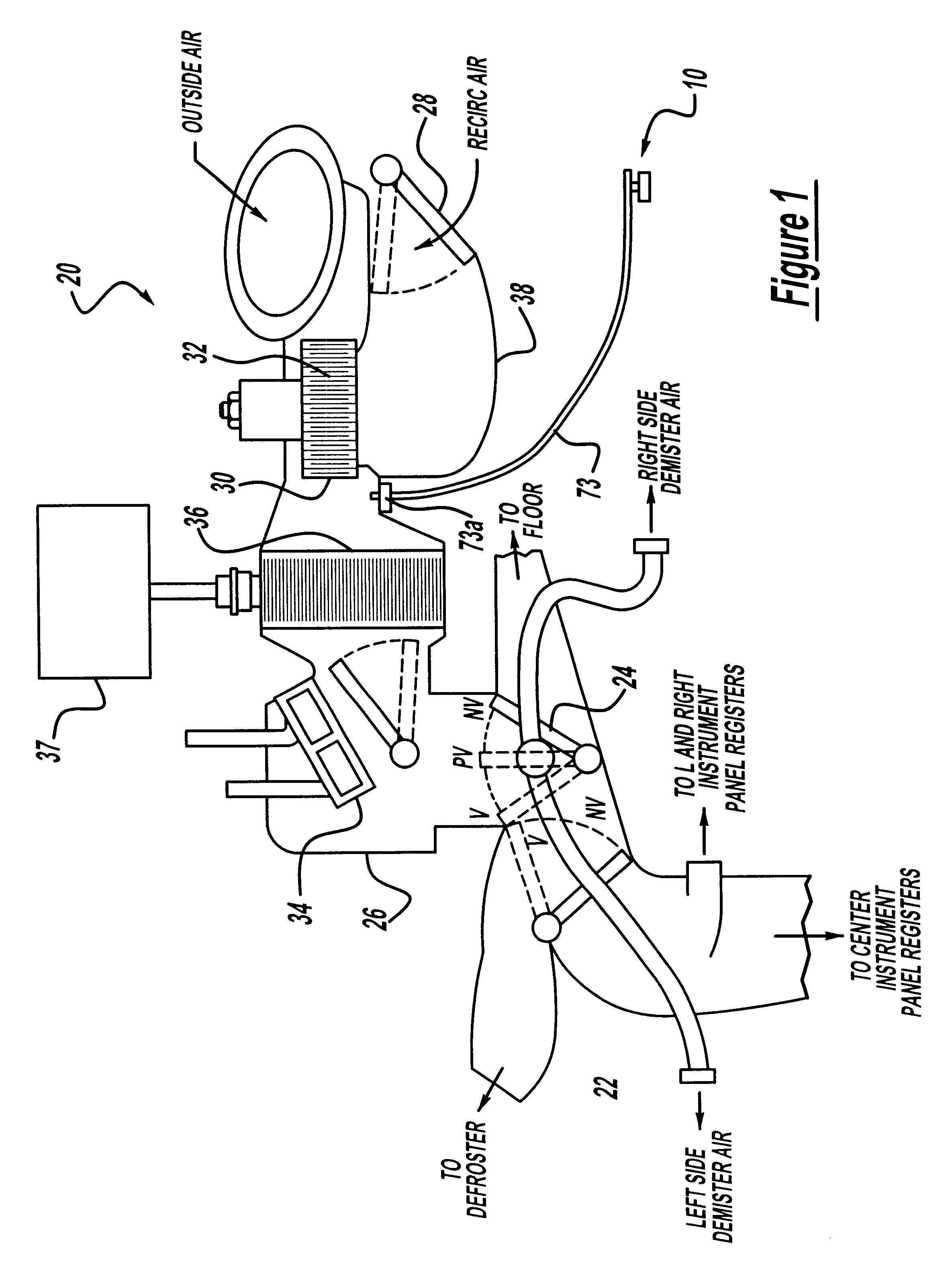
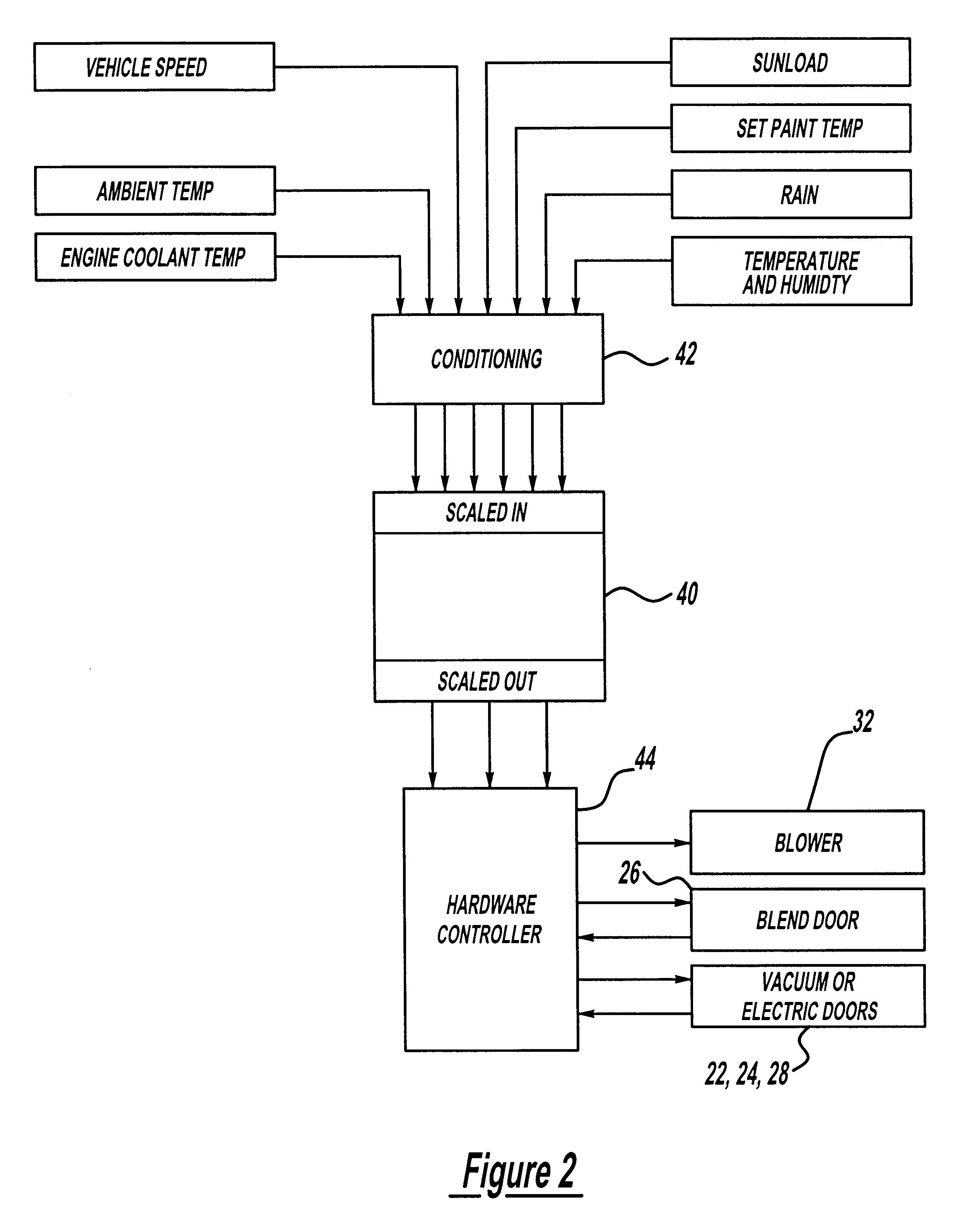
Referring to the drawings and in particular FIGS. 1 and 2, one embodiment of an air handling system of a heating, ventilation and air conditioning (HVAC) system 20 for a vehicle (not shown) is illustrated. In general, control of air temperature and airflow (and, to a lesser extent, humidity) within the vehicle is accomplished using various actuators to affect the temperature and flow of air supplied to a cabin or occupant compartment of the vehicle. The HVAC system 20 includes an arrangement of air flow doors, including panel-defrost, floor-panel, temperature blend and outside recirculated air actuators or doors 22, 24, 26 and 28, respectively. The doors 22 and 24 are driven by vacuum or electric motors (not shown) between their various positions in a conventional manner as illustrated in FIG. 1. The door 26 is driven by an electric servomotor (not shown) also in a conventional manner. The door 28 may also be driven by an electric servomotor so that the position of the door 28 is c...


PUM


Abstract

A temperature and humidity sensor assembly for a heating, ventilation and air conditioning (HVAC) system of a vehicle includes a housing for connection to the HVAC system. The temperature and humidity sensor also includes a humidity sensor disposed within the housing and a temperature sensor disposed within the housing. The temperature and humidity sensor further includes a circuit board disposed in the housing and electrically connected to the humidity sensor and the temperature sensor and for connection to an electronic controller to control the HVAC system.

Description

1. Field of the InventionThe present invention relates generally to heating, ventilating and air conditioning (HVAC) systems of vehicles and, more specifically, to a temperature and humidity sensor for a HVAC system in a vehicle.2. Description of the Related ArtIt is known that a fundamental goal of a HVAC system for a vehicle is to detect and avoid windshield / window fogging conditions. In an attempt to measure and control the many variables that affect fogging, modern HVAC systems have many sensors and control actuators. A typical HVAC system might have a temperature sensor inside an occupant compartment or cabin of the vehicle, one measuring ambient temperature outside and others measuring various temperatures of the HVAC system internal workings. The occupant may have some input to the HVAC system via a set point or other adjustment. Additional sensors measuring sun heating load, humidity, etc. might be available to the HVAC system. The set of actuators might include a variable s...

Claims


Application Information

Patent Timeline
Patent Type & Authority Patents(United States)
IPC IPC(8): B60H1/00G05D22/02G05D23/20G05D22/00G05D27/00G05D27/02G05D23/24
CPCB60H1/00785G05D22/02G05D27/02G05D23/24Y10S236/19
Inventor DAGE, GERHARD ALLANHOESCHELE, JOHN DAVIDDAVIS, JR., LEIGHTON IRA
Owner VISTEON GLOBAL TECH INC
Why Eureka
Try Eureka