Hold open arm assembly

a technology of arm and wing, which is applied in the direction of hinges, wing accessories, manufacturing tools, etc., can solve the problems of difficult to design a guide with suitable properties for both functions, metal to metal contact between the guide and the guide slot, and the load on the door can be quite high

Inactive Publication Date: 2002-02-19
BILCO
View PDF19 Cites 18 Cited by
  • Summary
  • Abstract
  • Description
  • Claims
  • Application Information

AI Technical Summary

Benefits of technology

The arm guide bracket is mounted to the door and the guide slot defines a guide slot plane offset from the arm axis. A stop is mounted offset from the guide slot plane in approximate alignment with the arm axis when the door is in the open position. The stop contacts the stop surface on the arm and prevents motion of the door from the open to the closed position when a closing force is applied directly to the door.
The guide slot is preferably tapered to securely hold the guide at one end when the door is closed and allows motion of the guide perpendicular to the axis of the guide slot when the door is open. The perpendicular motion causes the stop to move into and out of engagement with the stop surface of the arm.

Problems solved by technology

Because such doors are heavy, and because the non-vertical hinging of the door would cause the heavy door to rapidly swing closed when released, all such doors need hold open arm assemblies to hold them open.
Although hold open arm designs of the type described have been quite successful, one difficulty has been that the guide has served both the guiding function (to control the motion of the arm relative to the door) and the locking function (to prevent the door from closing unexpectedly).
It has been difficult to design a guide with suitable properties for performing both functions.
The load on the door can be quite high, particularly when the guide is preventing the door from closing under the unexpected application of a closing force.
This results in metal to metal contact between the guide and the guide slot.
Another disadvantage of earlier designs resides in the fact that the guide is offset from the longitudinal axis of the arm in order to engage the guiding slot.
This offset force application produces a significant bending moment on the arm when a large closing force is applied to the door.
The resulting load on the guide may tend to damage the guide or bend the arm.

Method used


Image

  • Hold open arm assembly
  • Hold open arm assembly
  • Hold open arm assembly

Examples


Embodiment Construction

)

In describing the preferred embodiment of the present invention, reference will be made herein to FIGS. 1-4 of the drawings in which like numerals refer to like features of the invention.

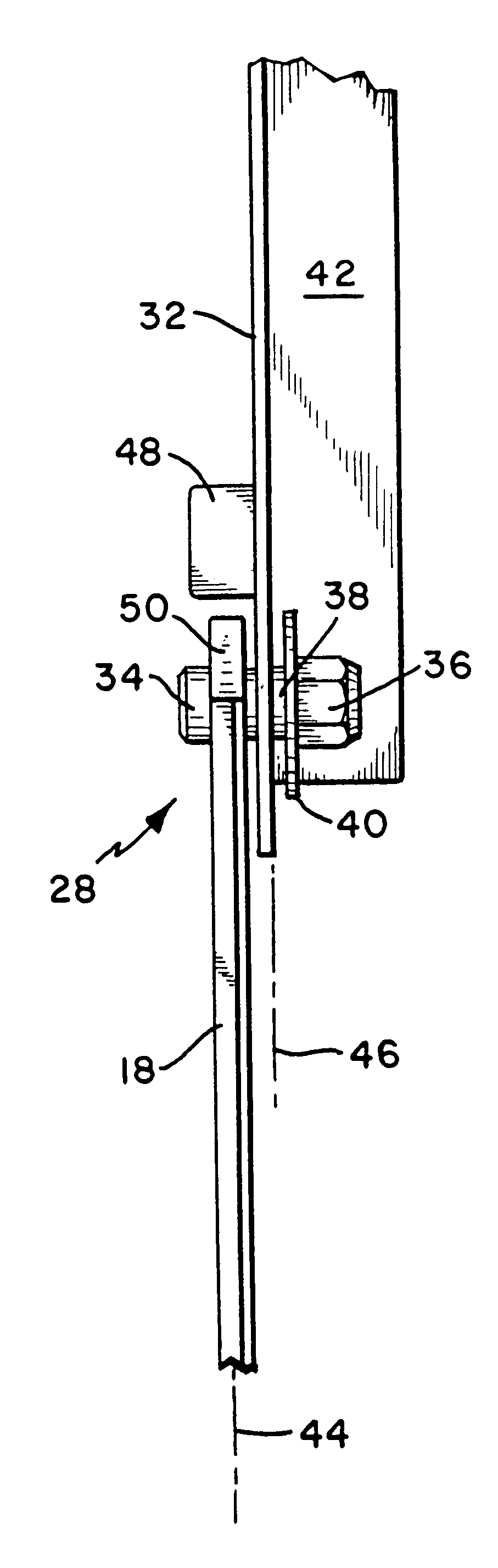
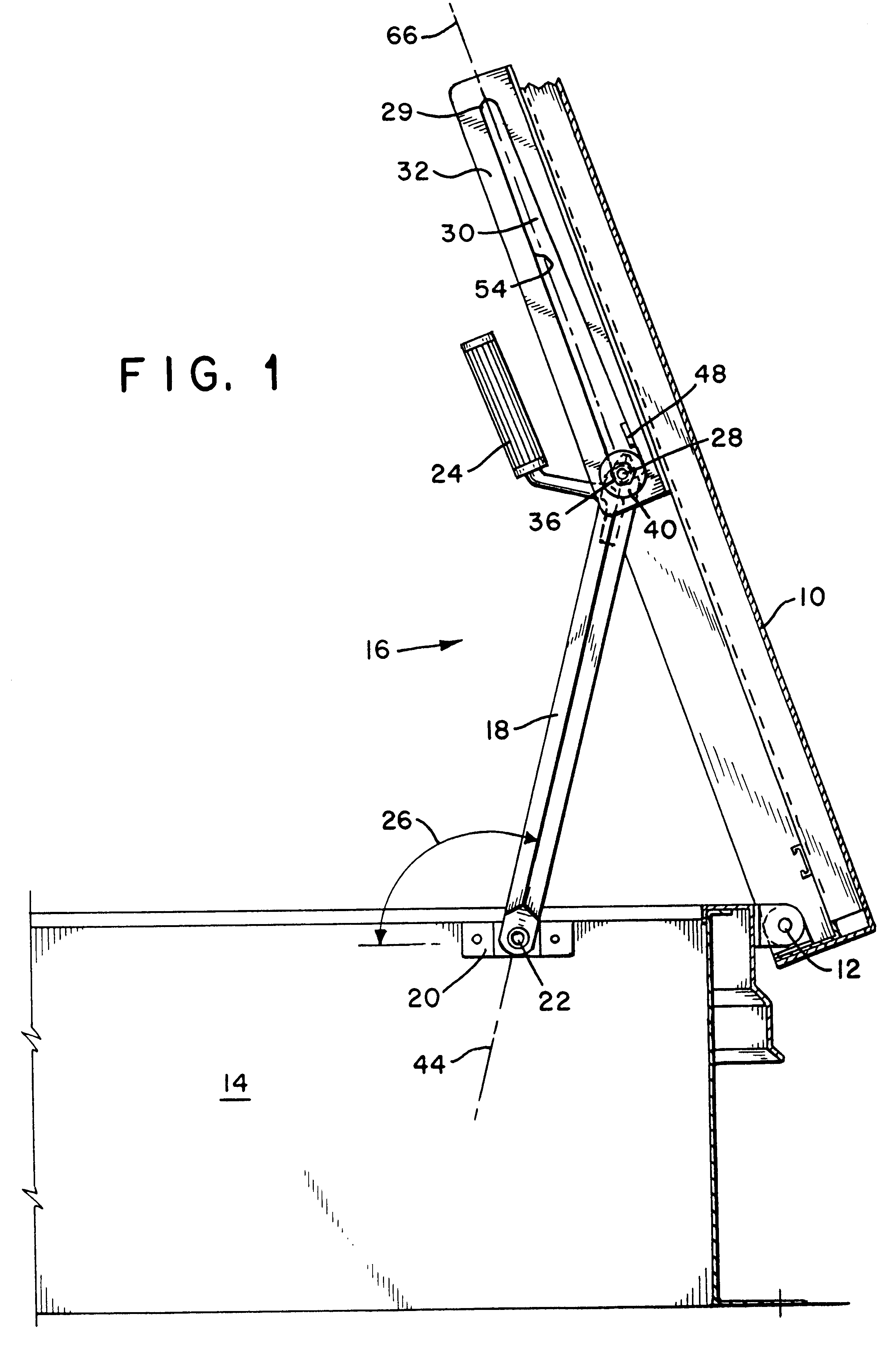
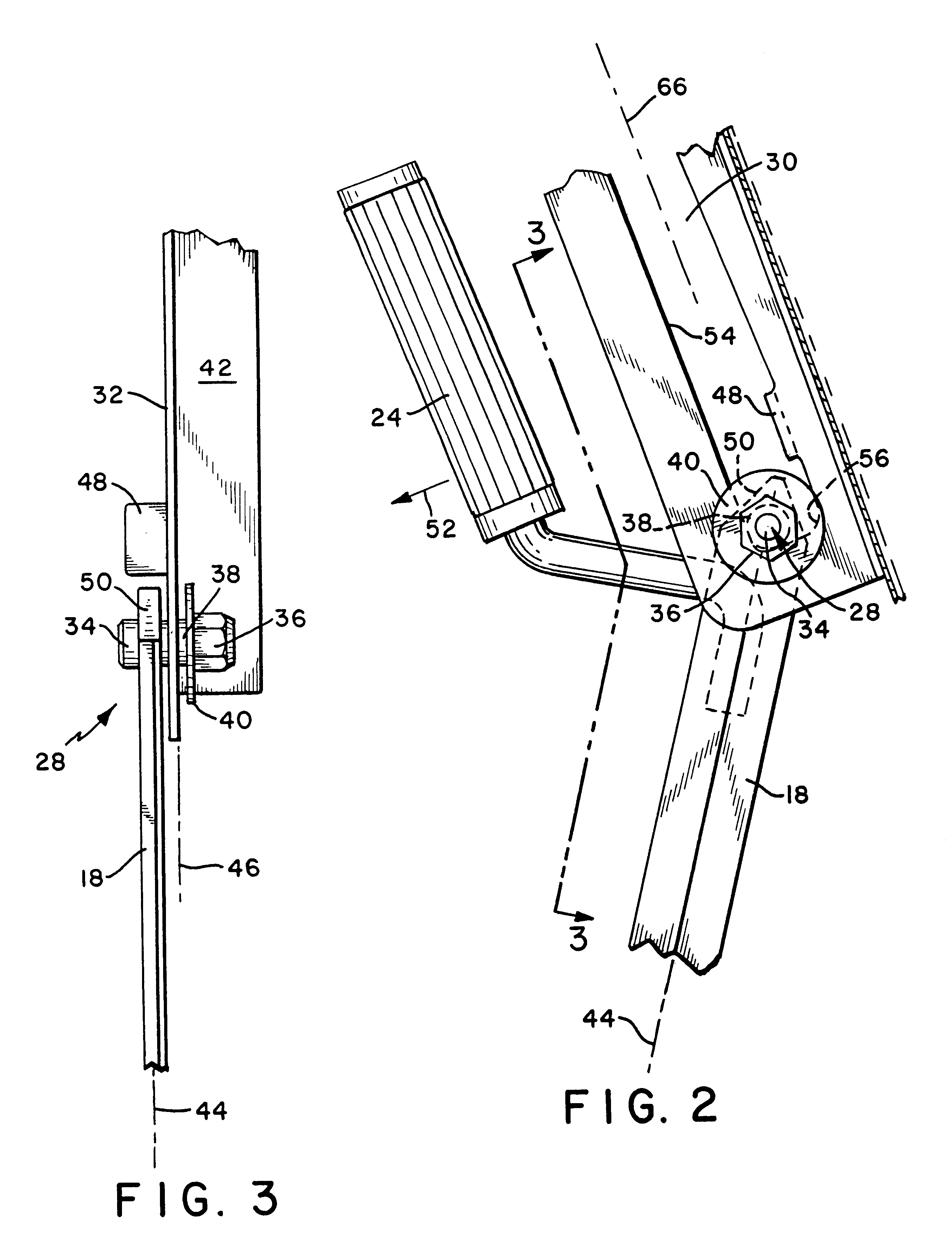
Referring to FIG. 1, the present invention is designed for installation on a door 10 that is non-vertically hinged on hinge 12 to a frame 14. The door may be a cover for a roof scuttle or any other type of door closing an opening in a roof or floor. The hinge line is usually horizontal, but it may also lie at any other angle to the vertical.

Typically, the door 10 will be counterbalanced with lift springs, torsion rods or other types of known counterbalancing systems. In the most typical application, the door 10 will be over counterbalanced such that there is a slight opening force on the door 10 when it is in the open position illustrated in FIG. 1.

The hold open arm assembly 16 of the present invention includes an elongated arm 18 extending between the door 10 and the frame 14. Arm 18 is pivotally ...


PUM


Abstract

A hold open arm assembly for a non-vertically hinged door prevents a door for a roof or floor opening from closing unexpectedly and allows one-handed operation. The assembly includes an elongated arm that bears directly against a stop aligned with the axis of the arm when a closing force, such as a wind load, is applied directly to the door. The arm has a guide that engages a guide slot in a bracket attached to the door. The guide slot is tapered and widens near the stop. When a closing force is applied to a handle connected to the arm, the guide moves parallel to the guide slot and the arm clears the stop, allowing the door to close. When the closing force is applied to the door, and not the handle, the guide moves perpendicular to the guide slot so that the arm engages the stop. The guide is provided with a low friction roller bearing for smooth operation.

Description

1. Field of the InventionThe present invention relates to devices for holding open hinged doors and covers of the type used for openings in roofs and floors.2. Description of Related ArtHatch covers, roof scuttles, floor doors and other types of openings in roofs and floors are provided with doors or covers that are hinged horizontally or at some angle to the vertical. The doors are typically heavy in order to support snow loads or traffic on their upper surface. Because such doors are heavy, and because the non-vertical hinging of the door would cause the heavy door to rapidly swing closed when released, all such doors need hold open arm assemblies to hold them open.For safety, most such doors are counterbalanced, but even fully counterbalanced doors are usually provided with a hold open arm assembly. The hold open arm assembly prevents the door from suddenly closing-for example under the influence of a sudden wind gust, or by someone leaning or falling against the door. Another ad...

Claims


Application Information

Patent Timeline
Patent Type & Authority Patents(United States)
IPC IPC(8): E04D13/03E04D13/035E05C17/00E05C17/24E05C17/04
CPCE04D13/0354E05C17/24E05C17/04Y10T16/5445Y10T16/5448Y10T292/297Y10T292/65
Inventor LYONS, SR., ROBERT J.
Owner BILCO
Why Eureka
Try Eureka