Ball joint type magnetic bearing for tilting body

a magnetic bearing and ball joint technology, applied in the direction of magnetic bearings, instruments, mechanical equipment, etc., can solve the problems of rapid loss of centering capability of magnetic bearings in connection with tilting facilities, and achieve the effect of increasing weigh

Inactive Publication Date: 2002-02-26
ALCATEL LUCENT SAS
View PDF13 Cites 33 Cited by
  • Summary
  • Abstract
  • Description
  • Claims
  • Application Information

AI Technical Summary

Benefits of technology

The object of the invention is to provide a magnetic bearing (sometimes referred to as a magnetic suspension) for centering a first body, which is mobile in tilting about a tilting center, relative to a second body, which system allows relative tilting through at least 5.degree., which tilting is significantly greater than that allowed by prior art magnetic bearings and can in particular reach or even exceed tilting angles of plus or minu

Problems solved by technology

However, as a general rule, magnetic bearings in connection with which the facility for tilting has been

Method used


Image

  • Ball joint type magnetic bearing for tilting body
  • Ball joint type magnetic bearing for tilting body
  • Ball joint type magnetic bearing for tilting body

Examples


Embodiment Construction

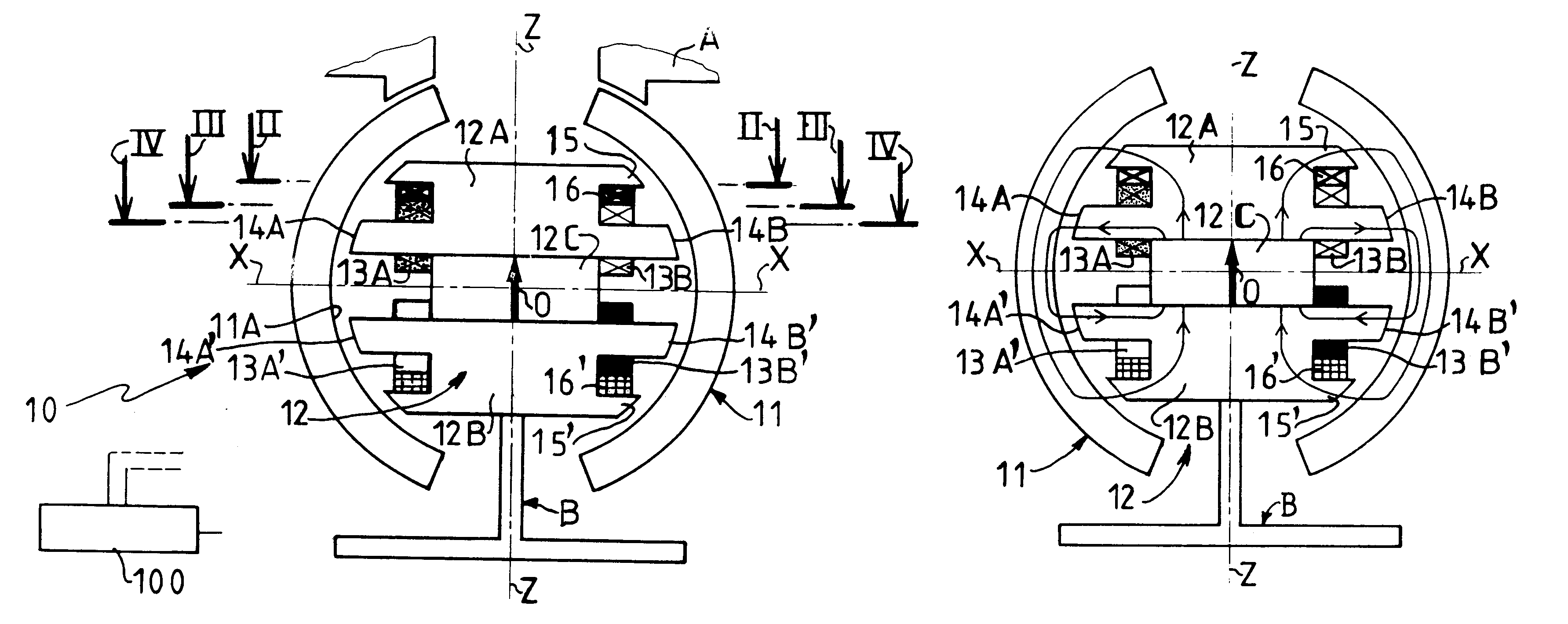
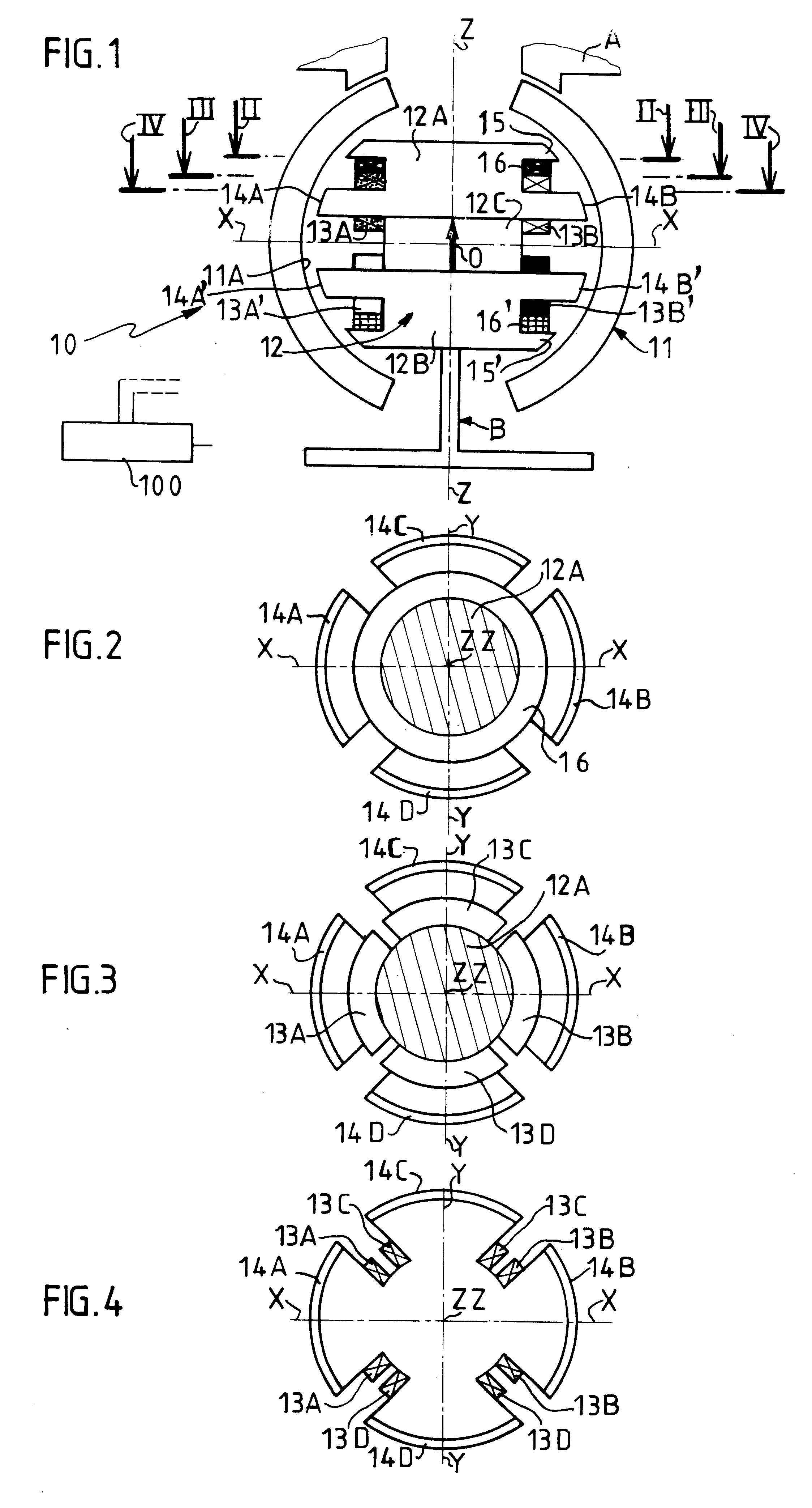
FIG. 1 shows a magnetic bearing 10 for centering a first body A, which can tilt within a range of angular movement of at least 5.degree. about a center O of tilting, relative to a second body B which has a vertical reference axis Z--Z passing through the center of tilting.

The magnetic bearing has a hollow outer part 11 fastened to the first body A and an inner part 12 fastened to the second body B.

The hollow outer part 11 has an inside surface 11A whose shape is a portion of a sphere whose center is substantially coincident with the center O of tilting. The hollow outer part extends completely around the reference axis Z--Z on both sides of a transverse plane perpendicular to the reference axis passing through the center O of tilting. In FIG. 1, that transverse plane is defined by an axis X--X transverse to the reference axis Z--Z at point O.

The hollow outer part 11 is at least partly made from a ferromagnetic material of any suitable type known in the art.

The inner part 12 includes...


PUM


Abstract

A magnetic bearing for centering a first body, which is mobile in tilting, relative to a second body includes:a hollow outer part at least part of which is made from a ferromagnetic material and which is attached to the first body and which has an inside surface whose shape is a portion of a sphere,an inner part which is attached to the second body and which includes two separate members which are separated by a space and which each include a plurality of (at least three) ferromagnetic areas which are offset angularly about the reference axis, which each define in conjunction with the inside surface of the hollow outer part two air-gaps offset relative to the reference axis and which are each provided with a specific winding adapted to generate magnetic flux lines closing across the two air-gaps, andan excitation circuit for selectively applying excitation currents to the windings.

Description

The invention relates to a magnetic bearing for magnetically centering a moving body relative to a fixed body with respect to three axes and preferably for controlling tilting of the moving body.Magnetic centering of one body relative to another body with respect to a given axis can be passive or active, depending on whether the centering magnetic fluxes are generated passively by permanently magnetized means or at least in part actively by an appropriate choice of the amplitude of an excitation current applied to windings. This is known in the art.For physical reasons, a body cannot be passively centered relative to another body with respect to three non-coplanar axes.For a given level of centering performance, the use of permanent magnets has the advantage of minimizing the electrical energy required for centering, compared to a configuration with no magnets.In practice, the body which is to be centered relative to a fixed body can have various degrees of freedom relative to the f...

Claims


Application Information

Patent Timeline
IPC IPC(8): F16C39/06F16C39/00F16C11/06
CPCF16C11/06F16C32/044Y10T74/1282Y10T74/125
Inventor CHASSOULIER, DAMIENCHILLET, CHRISTIANDELAMARE, JEROMEYONNET, JEAN-PAUL
Owner ALCATEL LUCENT SAS
Why Eureka
Try Eureka