
Extracting and positioning structure for hard disk drive

a technology for extracting and positioning structures, applied in the direction of electrical apparatus casings/cabinets/drawers, furniture parts, instruments, etc., can solve the problems of inconvenient use and bulkiness, and achieve the effect of simple structur

Inactive Publication Date: 2002-02-26
LITE ON ENCLOSURE
View PDF3 Cites 120 Cited by
  • Summary
  • Abstract
  • Description
  • Claims
  • Application Information

AI Technical Summary

Benefits of technology

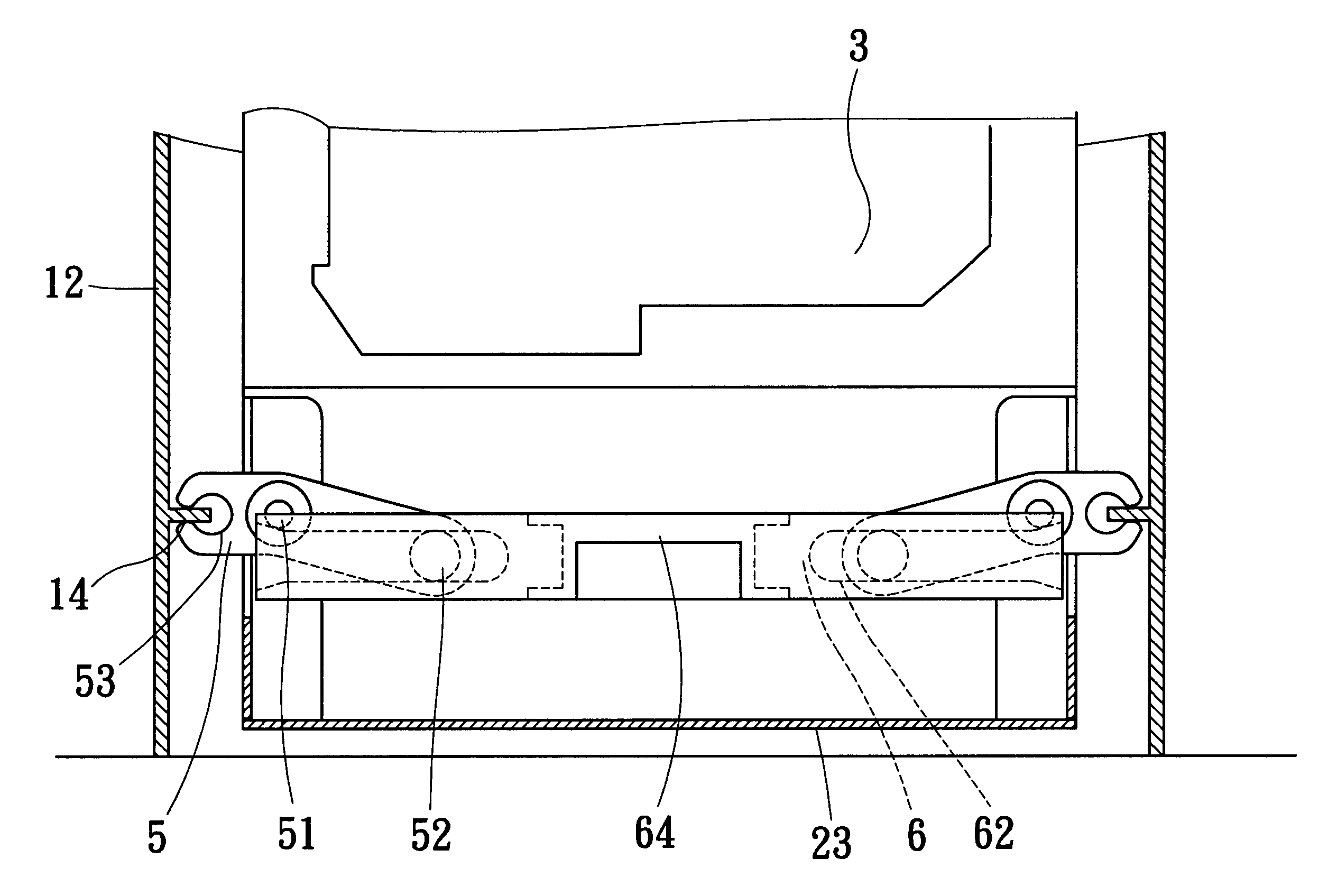
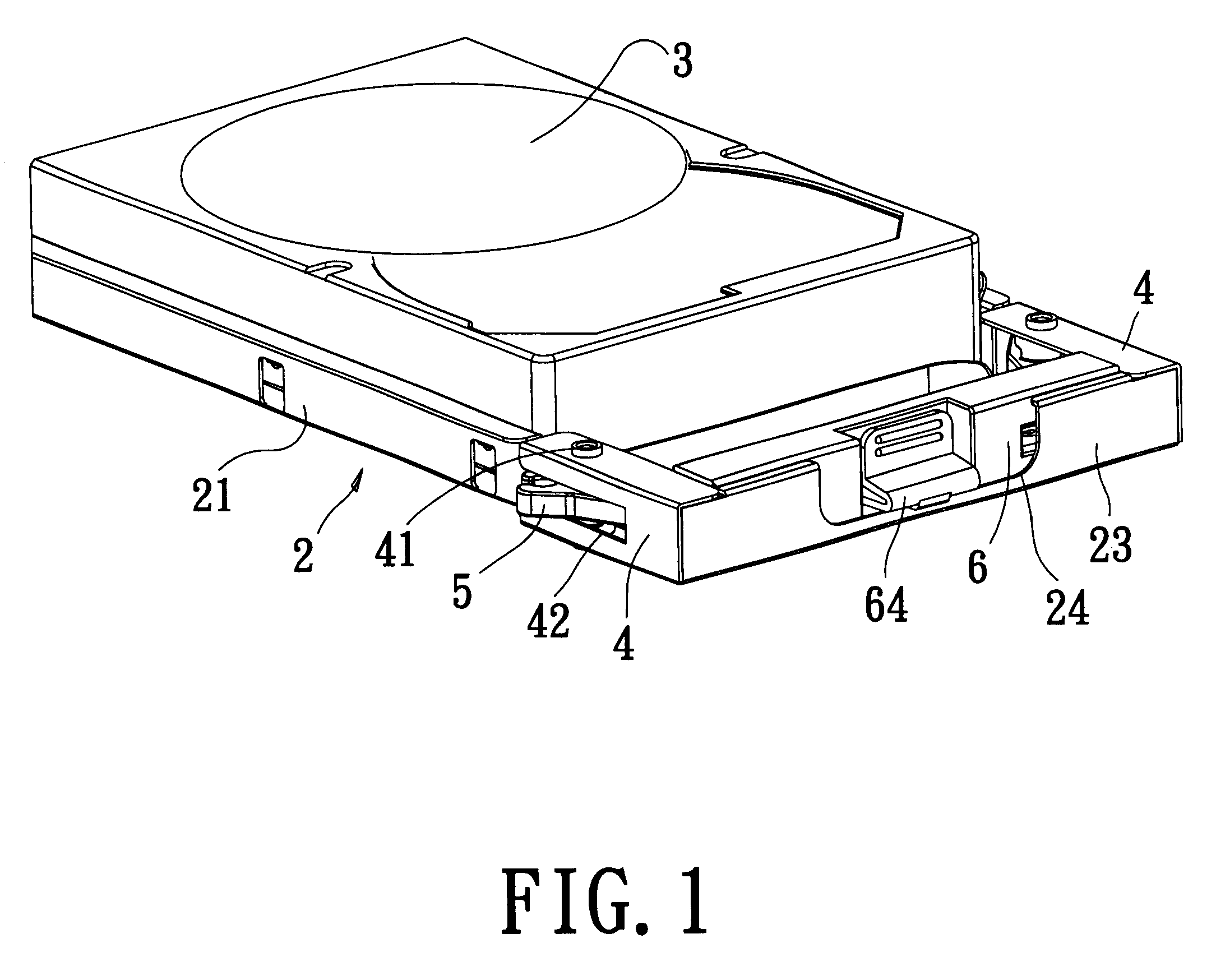
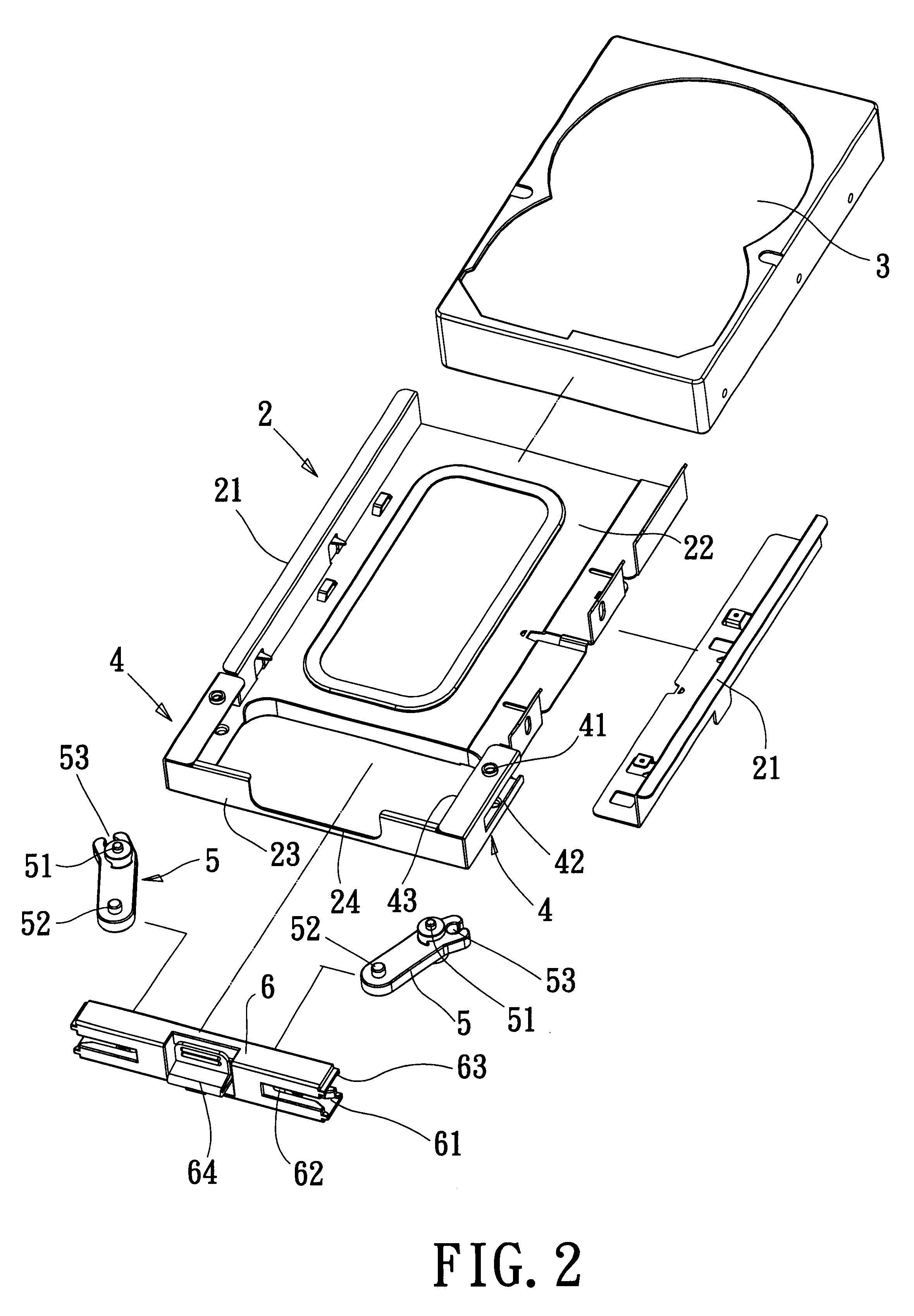
The object of the present invention is to provide an extracting and positioning structure for a hard disk drive. For an industrial computer, because a large amount of data needs to be proceeded, a disk raid of hard disk drives are generally installed, some used for storing back-up files, some used for storing working files, while some used for storing data files. There are many opportunities of replacing the hard disk drives. If the method of prior art is adopted, inconvenience and bulkiness may arise in use. The present invention can provide an extractable case with a simpler structure to bear the hard disk drive. Moreover, through the operation of a pair of pivotal retaining elements matched with a slide lever, the pivotal retaining elements can be positioned on side frame boards of the frame of a computer so that the extractable case can be fixed and positioned.

Problems solved by technology

If the method of prior art is adopted, inconvenience and bulkiness may arise in use.

Method used


Image

  • Extracting and positioning structure for hard disk drive
  • Extracting and positioning structure for hard disk drive
  • Extracting and positioning structure for hard disk drive

Examples


Embodiment Construction

As shown in FIGS. 1 to 6, the present invention proposes an extracting and positioning structure for a hard disk drive suitable to an industrial computer. Two side frame boards 12 are installed in a frame 11 of a computer 1 to receive and fix at least a hard disk drive. Latticed partitioning plate 13 is installed on the frame boards 12. The present invention has at least an extractable case 2. A fixing bar 21 is installed at each side of the extractable case 2. A hard disk drive 3 is joined with the fixing bars 21 to be fixed in the extractable case 2. The joining positions of the hard disk drive 3 are near the rear of the extractable case 2 where the extractable case 2 has a bottom board 22. Two sides of the hard disk drive 3 are fixedly screwed with the fixing bars 21 via screws. U-shaped plates 4 are arranged at two sides of the front half section of the extractable case 2, respectively. Pivotal holes 41 are disposed at the top and bottom surfaces of the U-shaped plates 4, respec...


PUM


Abstract

The present invention proposes an extracting and positioning structure for a hard disk drive suitable to an industrial computer. In the present invention, two side frame boards to fix at least a hard disk drive are installed on a frame of a computer. Latticed partitioning plates are installed on the frame boards. The present invention has at least an extractable case with fixing bars installed at two sides thereof to fix a hard disk drive therein. A U-shaped plate is installed at each side of the front half section of the extractable case. Pivotal holes are respectively disposed at the top and bottom surfaces of the U-shape plate to pivotally connect a spindle protruding out of the top and bottom surfaces of a pivotal retaining element. A fixing shaft protruding out of the top and bottom surfaces at the other end of the pivotal retaining element. A slide lever is transversely arranged in the U-shaped plate at the front end of the extractable case. Transverse grooves extend from the side end surfaces at the two ends of the slide lever, respectively. Slide grooves are disposed in the transverse grooves to pivotally connect the fixing shaft to push the slide lever backwards. The other end of the pivotal retaining element will thus be pushed out of a groove hole at the side surface of the U-shaped plate and a retaining groove at the other end of the pivotal retaining element will be secured on the side frame boards. The extractable case of the hard disk drive can be extracted out by pulling the slide lever forwards.

Description

The present invention relates to an extracting and positioning structure for a hard disk drive and, more particularly, to a fixing structure having simpler but better positioning effect and suitable to an extractable hard disk drive used in an industrial computer.An extractable hard disk drive in prior art comprises a hard disk drive, an inner case for receiving the hard disk drive, and a fixing seat. The fixing seat can slide in or out between a pair of fins of fixing racks in the housing of a computer. Generally, the fixing seat is fixedly screwed while the inner case slides in or out of the fixing seat to achieve the object of replacing the hard disk drive conveniently. The inner case is also replaced along with the hard disk drive. To facilitate the extraction of the inner case, a grip is installed at the outer end surface of the inner case. The grip can provide convenience for gripping and taking and is the position for exerting the extraction force. However, there is positioni...

Claims


Application Information

Patent Timeline
IPC IPC(8): G11B33/12
CPCG11B33/128
Inventor CHENG, KUANG JUI
Owner LITE ON ENCLOSURE
Learn More