Pouring spout for mounting on a container

a technology for pouring spouts and containers, which is applied in the direction of pliable tubular containers, transportation and packaging, cooking vessels, etc., can solve the problems of difficult pouring with containers without this handle, not particularly elegant or hygienic,

Inactive Publication Date: 2002-03-05
EVA SOLO
View PDF14 Cites 16 Cited by
  • Summary
  • Abstract
  • Description
  • Claims
  • Application Information

AI Technical Summary

Benefits of technology

Finally, as disclosed in claim 7, it is expedient to configure the seal as a resilient lip which can ensure both tightness and the securing of the pouring spout in the bottleneck.

Problems solved by technology

Containers without this handle are therefore difficult to pour with in a drip-free manner, since as mentioned it requires careful orientation in order to ensure that the liquid flows precisely in the outflow groove.
Where wine bottles are concerned, the same problem arises when using pourers.
However, this solution is encumbered with the disadvantage that the liquid runs on the outside of the bottle, which is not particularly elegant or hygienic.
To this is added the problem of securing the sleeve on the neck of the bottle, since bottles exist in many different sizes both in length and diameter.

Method used


Image

  • Pouring spout for mounting on a container
  • Pouring spout for mounting on a container
  • Pouring spout for mounting on a container

Examples


Embodiment Construction

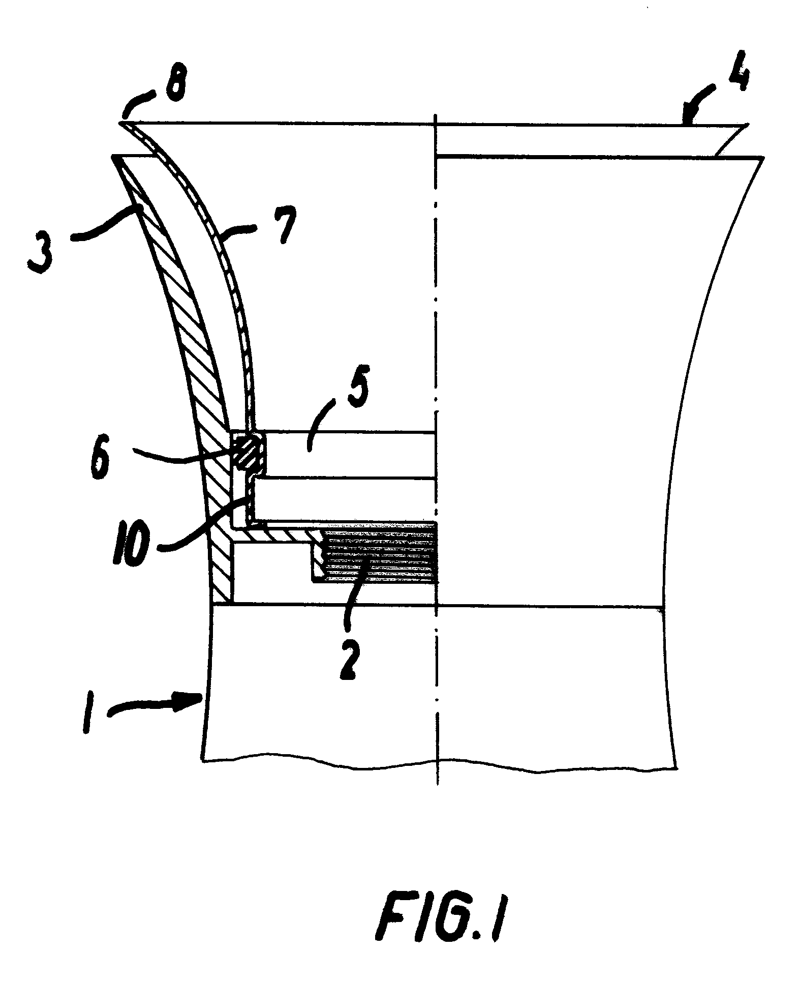
In FIG. 1 there is shown a first embodiment of a pouring spout for use on a thermos flask 1 or similar container.

The container does not have a handle, and its own pouring spout 3 is therefore configured as an annular collar which ends in an edge.

Without pouring spout, this container will have a tendency to drip liquid from the outflow spout.

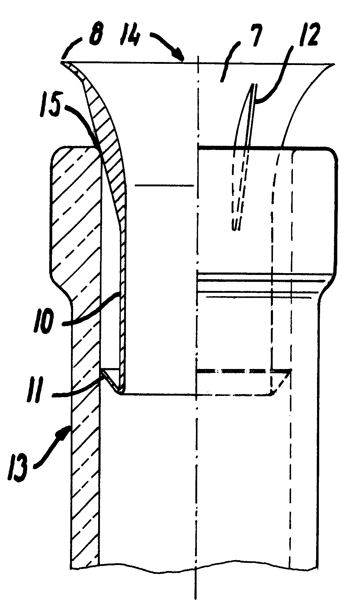
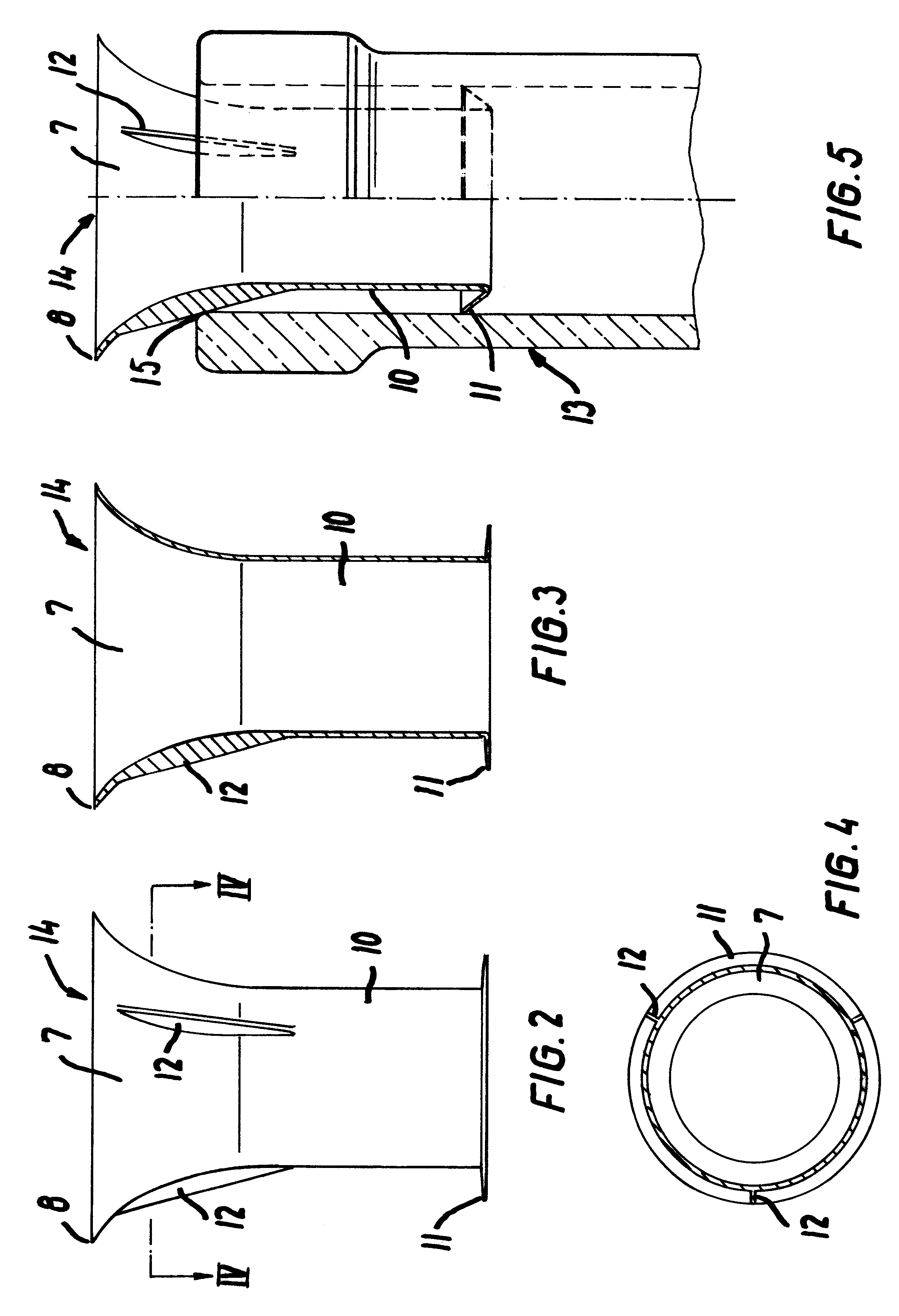
To avoid this, a pouring spout 4 according to the invention is mounted, said pouring spout being configured with a lower cylindrical collar 10 which rests against the top of the flask 1 with outflow hole 2 possibly with thread for a not-shown closing stopper.

On the collar 10 there is configured an annular groove or seating 5 for a sealing ring 6 which lies in a tightening manner up against the inside of the outflow edge 3 of the flask.

The upper part of the outflow spout 4 is configured as an outwardly-curving collar 7 which extends a small distance up over the edge 3 of the flask, and substantially to the same outward extent as this edge.

The coll...


PUM


Abstract

According to the invention, a pouring spout for mounting on a container's neck can be configured as a spout placed in the container's neck, which spout goes on the inside of the neck so that possible drops of liquid will be collected inside the neck. Drops of liquid running on the outside of the container are hereby avoided and at the same time it is achieved that the container can pour in all directions since the edge of the pouring spout extends uniformly around the container's neck.

Description

The invention concerns a pouring spout for mounting on the neck of a container, the neck of a flask or a bottleneck, said pouring spout forming a channel between its outer side and the inside of the neck for the collection of possible drops of liquid when the container is raised upright after the pouring-out.When pouring liquids out of a container, such as a thermos flask or bottle, liquid will often be left remaining on the spout which, when the container is raised, possibly collects in drop form and drips down or runs down the container.Many attempts have been made to eliminate this disadvantage, especially in the form of diverse configurations of separate pouring spouts.However, it is common to all these pouring spouts that the way in which they function is based on outflow in one and only one direction, i.e. in a groove or channel which terminates in one or another kind of edge. The risk that the liquid can collect at the edge area is hereby reduced, but in the case of liquid, t...

Claims


Application Information

Patent Timeline
Patent Type & Authority Patents(United States)
IPC IPC(8): A47G19/00A47G19/14A47J36/14A47J36/00B65D23/00B65D23/06
CPCA47G19/145B65D23/065A47J36/14
Inventor ANDERSEN, BJARNE BOHOLB.AE BUTTED.K, HENRIKJENSEN, CLAUSE
Owner EVA SOLO
Why Eureka
Try Eureka