
Cable TV end connector starter guide

a technology for tvs and connectors, which is applied in the direction of connections, contact member assemblies/disassemblies, electrical equipment, etc., can solve the problems of poor fit between cables and connectors, inability to purchase crimping tools,

Inactive Publication Date: 2002-03-05
PPC BROADBAND INC
View PDF9 Cites 117 Cited by
  • Summary
  • Abstract
  • Description
  • Claims
  • Application Information

AI Technical Summary

Benefits of technology

Another object of the present invention is to provide for a novel and improved installation guide for connecting a coaxial cable to an end connector or for splicing two coaxial cables together which is low cost, requires a minimum number of assembly steps, assures precise alignment and sealed engagement between the parts, and prevents shorting between the electrically conductive foil layer on the cable and the conductor pin on the cable as well as conductor portions of the starter guide.
It is a further object of the present invention to provide for a novel and improved installation guide inserted into an end connector having a pre-installed crimping ring as a preliminary to insertion and crimping of a coaxial cable to the connector and in such a way that the installation guide can either be automatically discarded when the parts have become properly assembled or can remain in place as a part of the assembly.
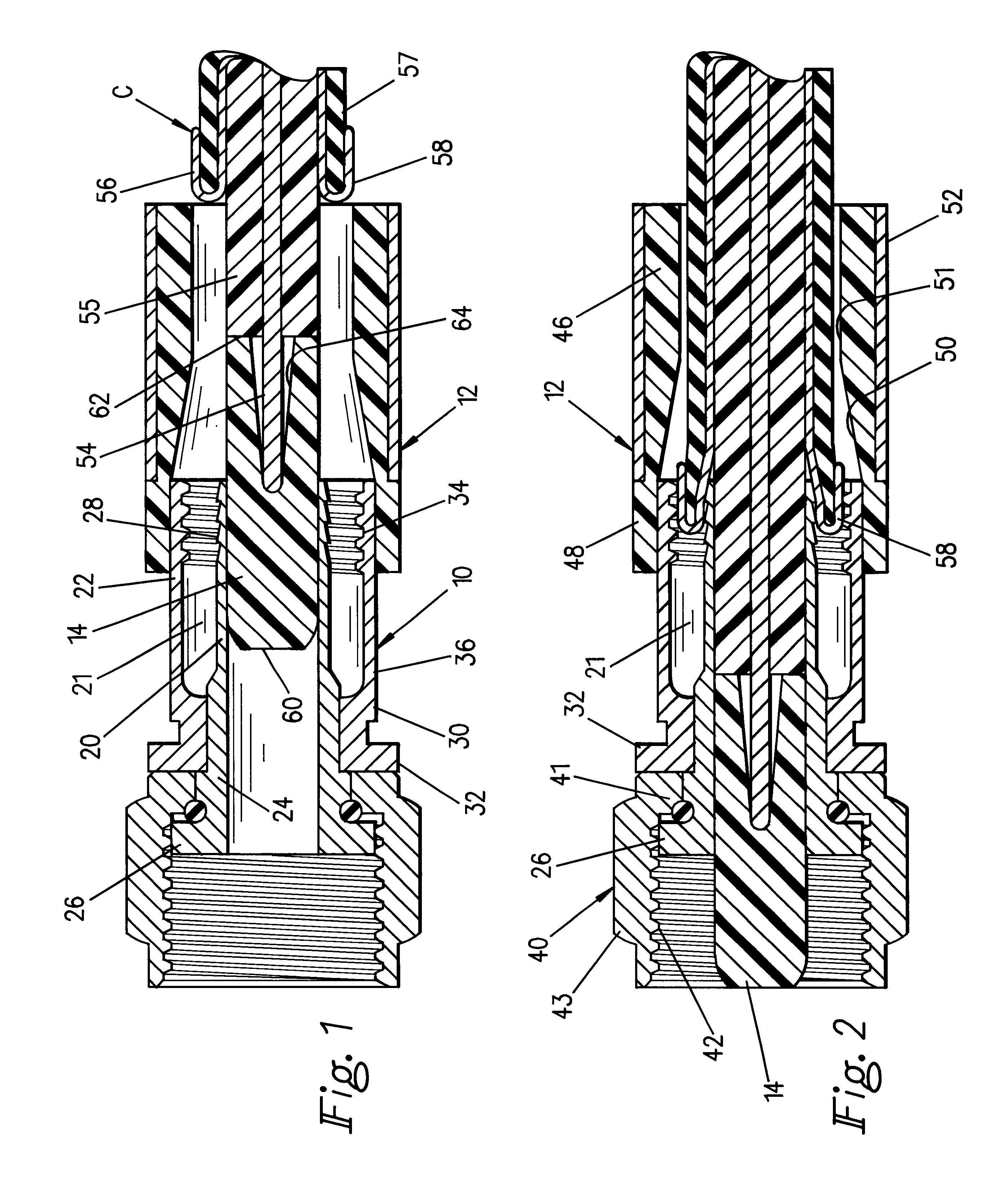
In accordance with the present invention, an installation guide has been devised which is comprised of an elongated insert adapted for insertion into engagement with an inner wall of the end connector and wherein the guide projects forwardly toward the entrance of the connector and is recessed at its forward end to receive the male end or electrically conductive pin portion of the cable to retain the cable in centered relation for insertion into sealed engagement as a preliminary to being joined to the connector, such as, by crimping. In one form, the installation guide is slidable rearwardly with the cable as it is advanced into mating relation to the end connector, and the guide is free to fall away from or be removed from the opposite end of the connector prior to connection of the cable to another cable or to a post or terminal, as the case may be.
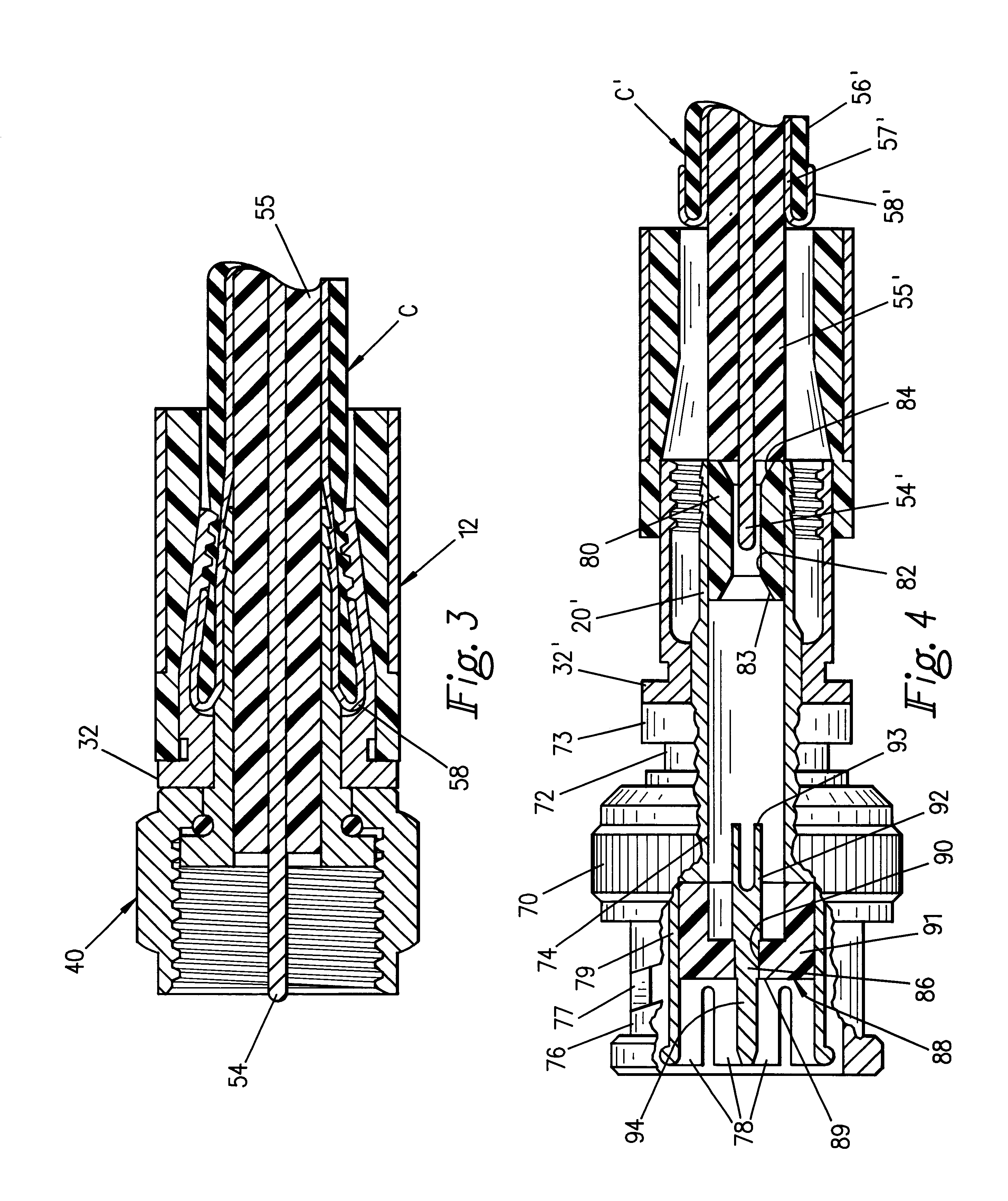
In another form of invention, the installation guide is in the form of a tubular insert placed in the inner wall of the end connector and defines a guide passage for advancement of the conductive portion of the cable therethrough and into engagement with another elongated conductor member at the one end of the connector opposite to insertion of the cable. This alternate form is adapted for use more with even greater length connectors than the first form, such as, a BNC connector in which an extension of the conductive portion of the cable is required in order to make the necessary electrical connection with the terminal. Accordingly, the guide insert itself is formed with a pin-receiving bore which is surrounded by seizure prongs which contract against the pin when the pin is inserted in to the bore. The guide tube itself is preinstalled into the inner sleeve to a first position and, when the conductor pin is inserted into the bore, the end of the dielectric surrounding the conductor pin will abut the end of the guide tube and force it rearwardly a limited distance until the pin itself becomes seized by the prongs at the opposite end of the connector to the entrance. Thus, the guide tube serves the dual purpose of an improved electrical connection with minimal return losses and proper alignment of the conductor pin and dielectric within the inner sleeve of the connector.
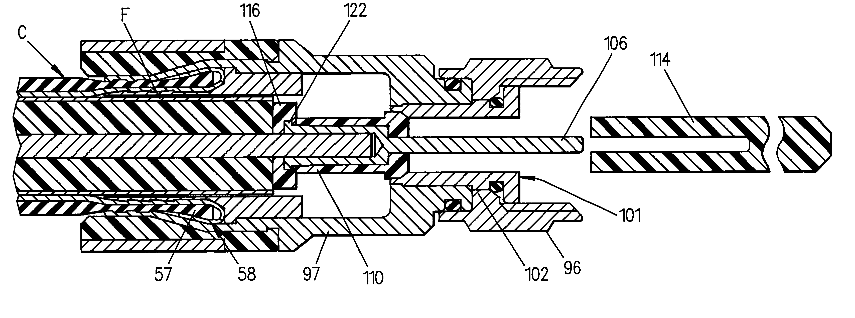
As a still further modification of the form of invention, the guide insert is in the form of an extension pin with a pin-receiving bore surrounded by seizure prongs to contract against the conductor pin of the cable when the latter is advanced through the crimping ring. However, in place of the tubular insert of the alternate form just described, the extension pin is preassembled into a starter plug which is supported at the front end of the end connector and in turn supports the extension pin in a position to receive the conductor pin on the cable as it is initially advanced through the crimping ring. The starter plug will fall off once the extension pin is advanced through the connector until the starter plug reaches a limit stop. In this way, the assembler can determine that the cable has been advanced the proper distance into the connector for complete assembly.
It is therefore to be understood that even though numerous characteristics and advantages of the present invention have been set forth in the foregoing description, together with details of the structure and function of the invention, the disclosure is illustrative only, and changes may be made within the principles of the invention to the full extent indicated by the broad general meaning of the terms in which the appended claims are expressed and reasonable equivalents thereof.

Problems solved by technology

However, it was found that there are a number of situations in which it was not feasible to purchase a crimping tool or where a crimping tool was not available either to splice coaxial cables together or to connect one end of the cable via a connector fitting into a post or terminal.
As a result, in attempting to insert the pin member and surrounding dielectric into the sleeve, if not properly centered, makes it difficult to properly insert the outer jacket and braided conductor layer of the cable into the annular space between the inner and outer sleeves of the connector body without damaging or distorting the outer layers but in any event can result in an extremely poor fit between the cable and connector as a preliminary to the crimping operation.

Method used


Image

  • Cable TV end connector starter guide
  • Cable TV end connector starter guide
  • Cable TV end connector starter guide

Examples


Embodiment Construction

Referring in more detail to the drawings, there is shown by way of illustrative example in FIGS. 1 to 3, one standard form of end connector 10 of the type having a crimping ring 12 at one end through which an installation guide 14 is inserted to facilitate assembly and attachment of a standard coaxial cable represented at C to the connector 10. The end connector 10 is broadly comprised of a concentrically spaced inner sleeve 20 and outer sleeve 22, the inner sleeve having any inner wall surface 21 which defines the smallest diameter of the opening or bore through the end connector 10 and verges into a cylindrical body 24 which terminates in an external shoulder 26. The inner sleeve 20 includes a plurality of external serrations 28 angled in a direction away from the entrance end of the connector 10 which receives the cable C.

The outer sleeve 22 similar includes a cylindrical body 30 and an external shoulder 32 at one end opposite to a series of ribs or endless rings 34 in facing rel...


PUM


Abstract

A guide for coaxial cable end connectors having a crimping ring at one end of the connector which receives the end of the coaxial cable, a cylindrical insert disposed in a central bore of the connector body and has a recessed portion for loose-fitting insertion of the cable to maintain centered to the body as the cable is advanced with the body. In one form, the guide is free to be removed from the body once the cable is fully inserted, and in another form has a tubular insert through which the cable is inserted and advanced into engagement with an extension pin with the tubular insert in surrounding relation to the extension pin. In one form, a starter plug supports an extension pin in the body and facing the male end of the cable so that the male end will advance the extension pin toward the opposite end of the connector body as the cable is advanced into the body.

Description

BACKGROUND AND FIELD OF INVENTIONThis invention relates to installation guides; and more particularly relates to novel and improved installation guide for coaxial cable end connectors used in splicing the cable to another cable or connecting to a post or terminal.I have previously devised end connectors for effecting sealed engagement with one end of the coaxial cable by applying a crimping force to a sleeve on the connector body which will uniformly reduce the diameter of the sleeve into a generally conical configuration which snugly engages the end of the cable, reference being made to U.S. Pat. Nos. 5,392,508 and 5,596,800. End connectors of the type disclosed in those patents require the use of a separate crimping tool and are primarily intended for use by professional cable installers. However, it was found that there are a number of situations in which it was not feasible to purchase a crimping tool or where a crimping tool was not available either to splice coaxial cables tog...

Claims


Application Information

Patent Timeline
Patent Type & Authority Patents(United States)
IPC IPC(8): H01R9/05H01R43/22H01R43/20
CPCH01R9/0521H01R43/22
Inventor HOLLIDAY, RANDALL A.WONG, SHENG CHIA
Owner PPC BROADBAND INC
Learn More